| The Overall Plan |
|
|
|
Overall
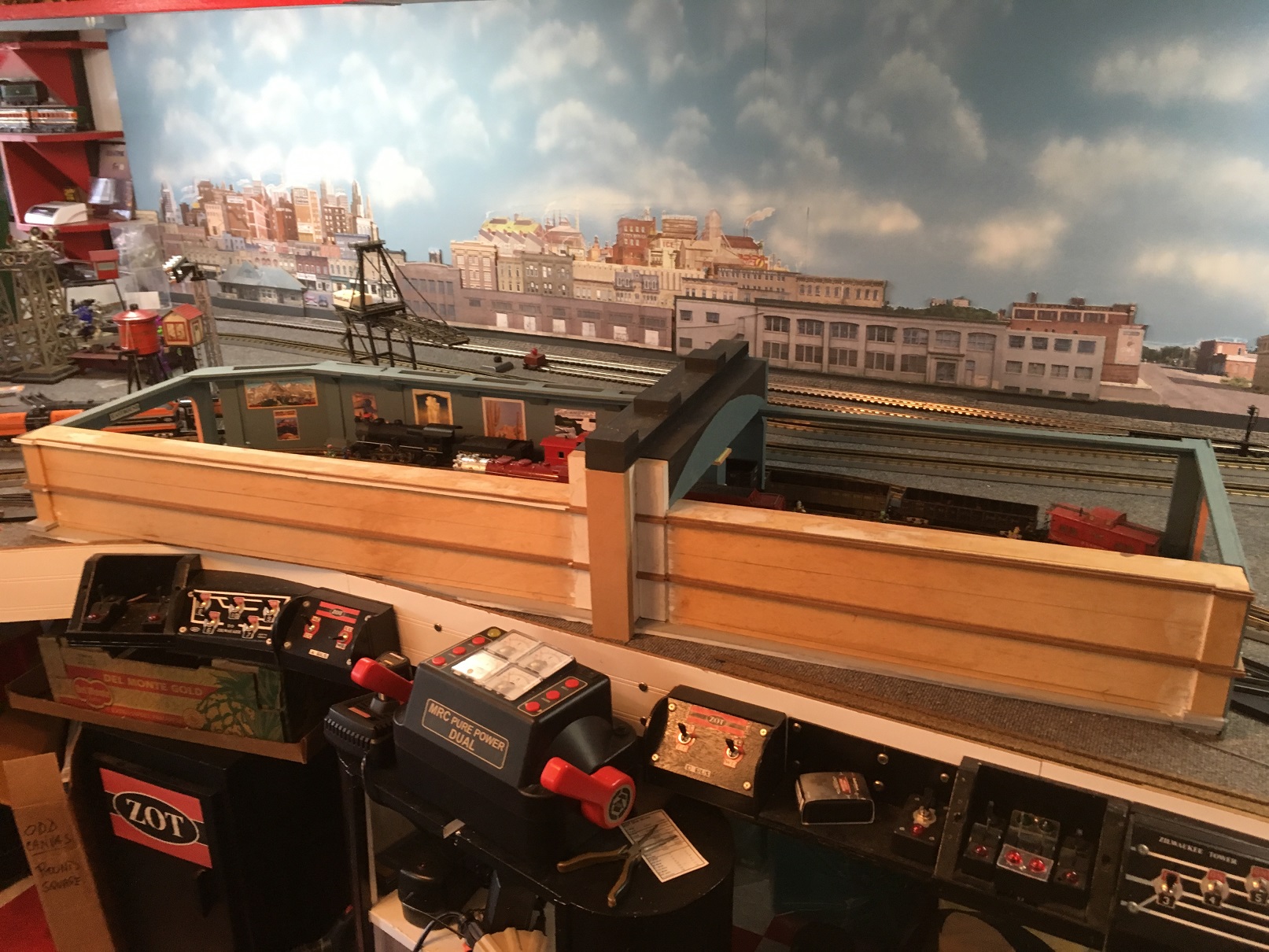
The overall view provides a look at the entire terminal area and the outer walls.
The station is being built in place. First the tracks were laid and then the ground-level platforms.
Next came the walls and the roof section in the center. It simulates an overhead walkway and the elevators that serve the people on the platforms.
The facade has some structure but no details. This view is looking to the south.
|
East End
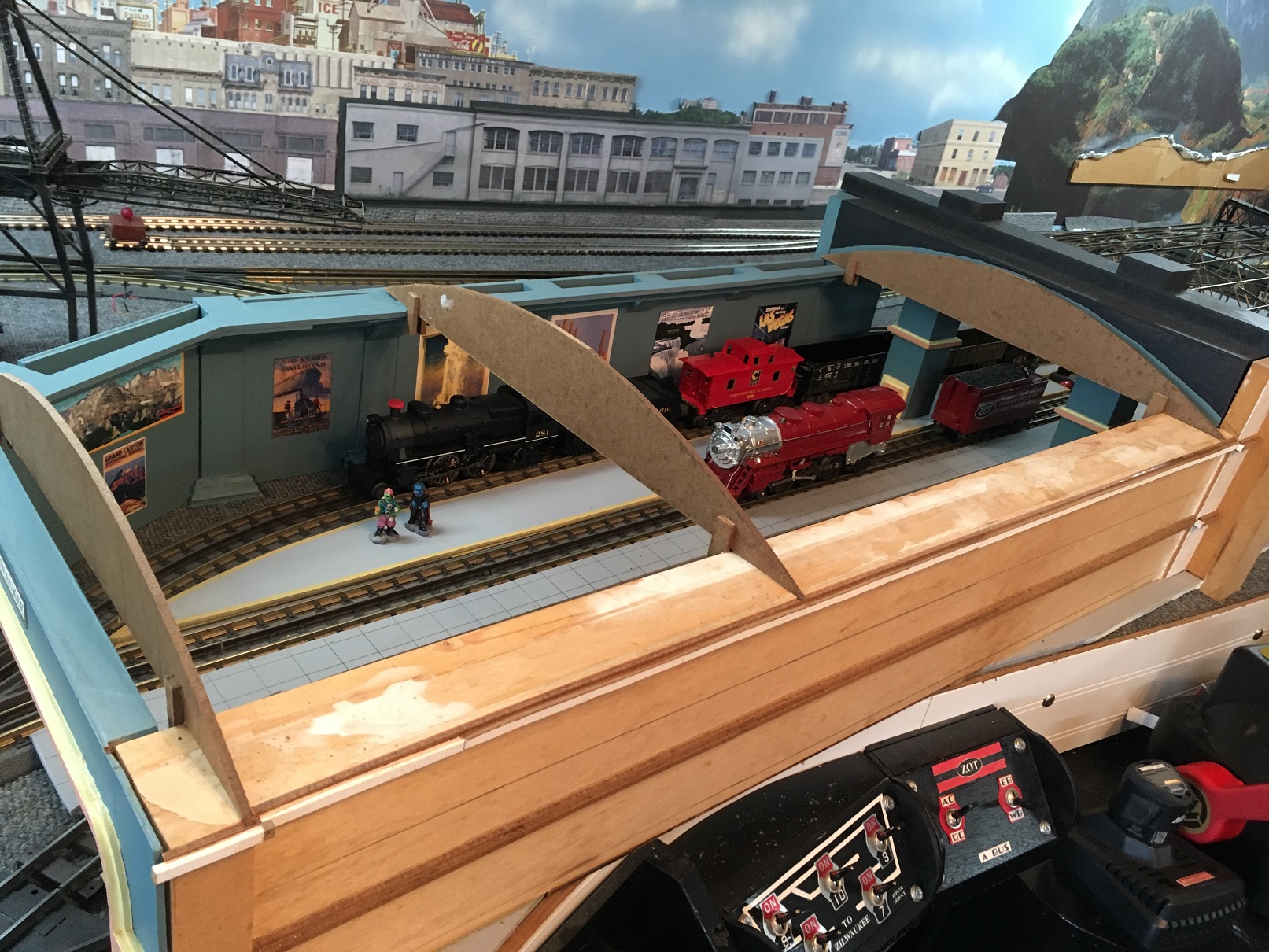
The longer end of the station faces outward to the west. At the westen end, you can see the
tracks begin to converge making the overall structure a little more interesting than a vanilla rectangle woould be.
The masonite pieces take the place of the roof trusses. They assist in visualizing the construction yet to come.
|
Inside East End
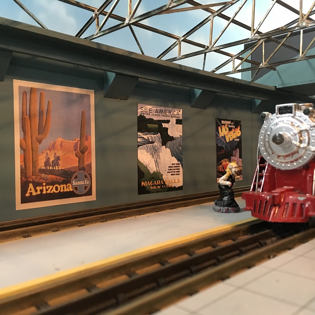
Here you can see a trackside view of the interior facing to the far wall. The posters are
captures from the Internet and sized to fit. Adds a little interest, don't you think?
|
|
|
|
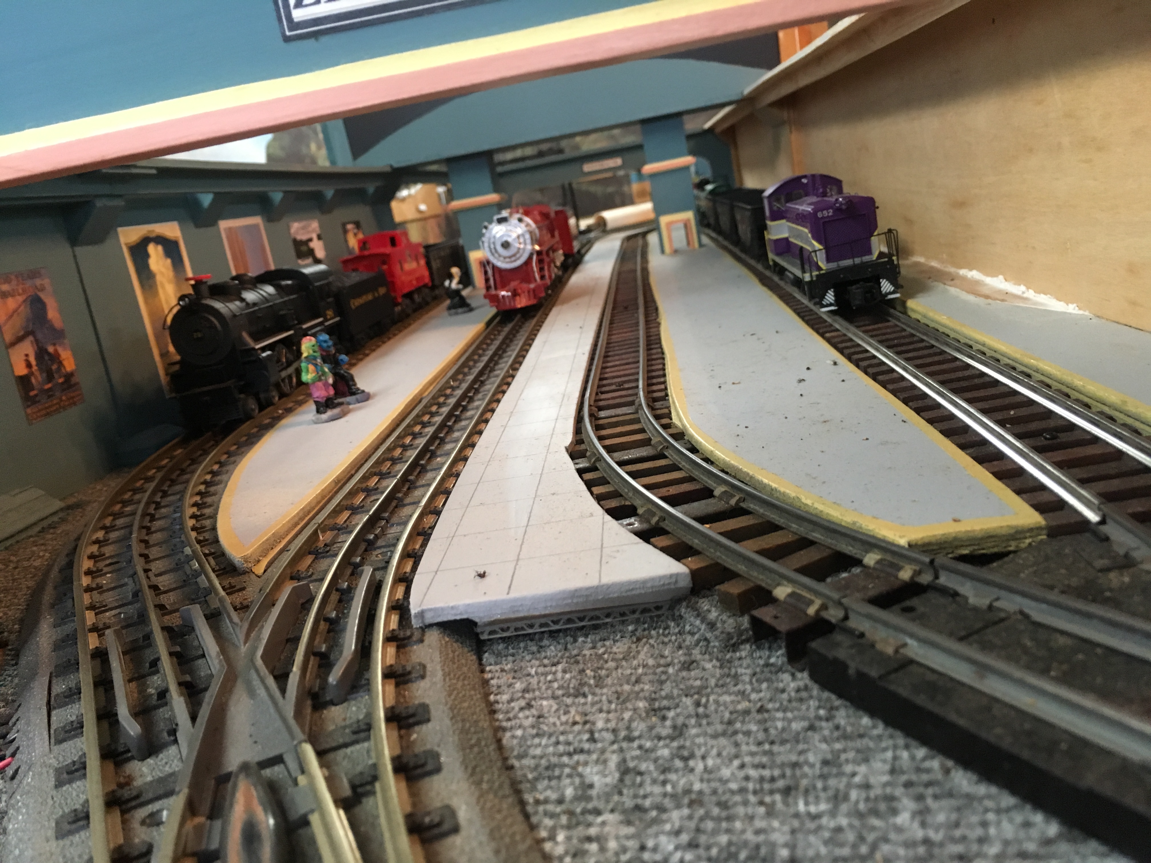
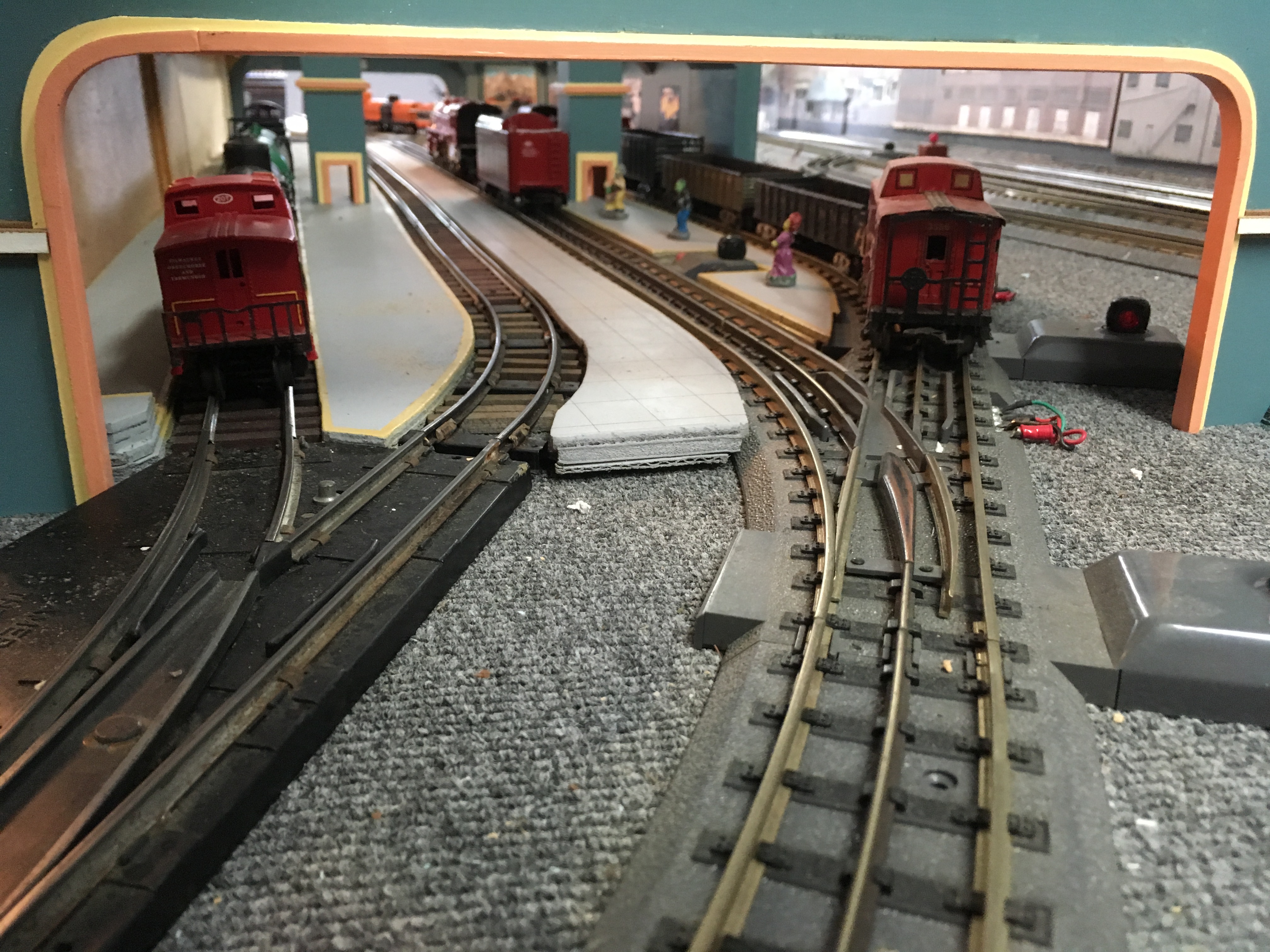
East End Track
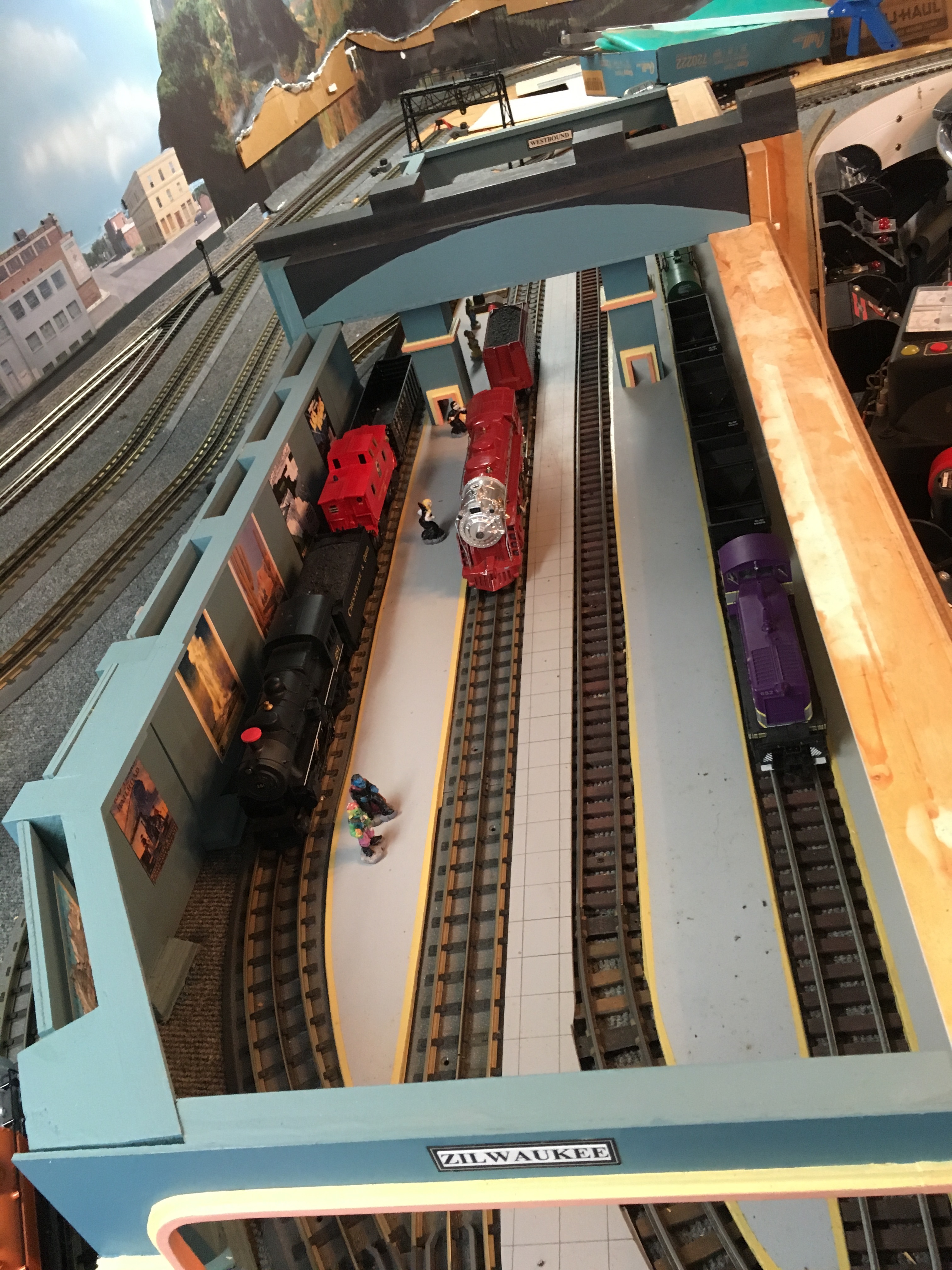
Here you can see the four tracks inside the terminal building. The two to the left of this image
are O-Gauge track used for 3/16ths scale, O-Gauge trains. Here you see a recent production Atlas and a much older Marx that has been repainted.
The two tracks to the right side are S-Gauge. The trains that run on them are S-Scale which is the same 1:64 scale we
get using 3/16ths inch per foot. You can see a recent production SHS diesel locomotive.
|
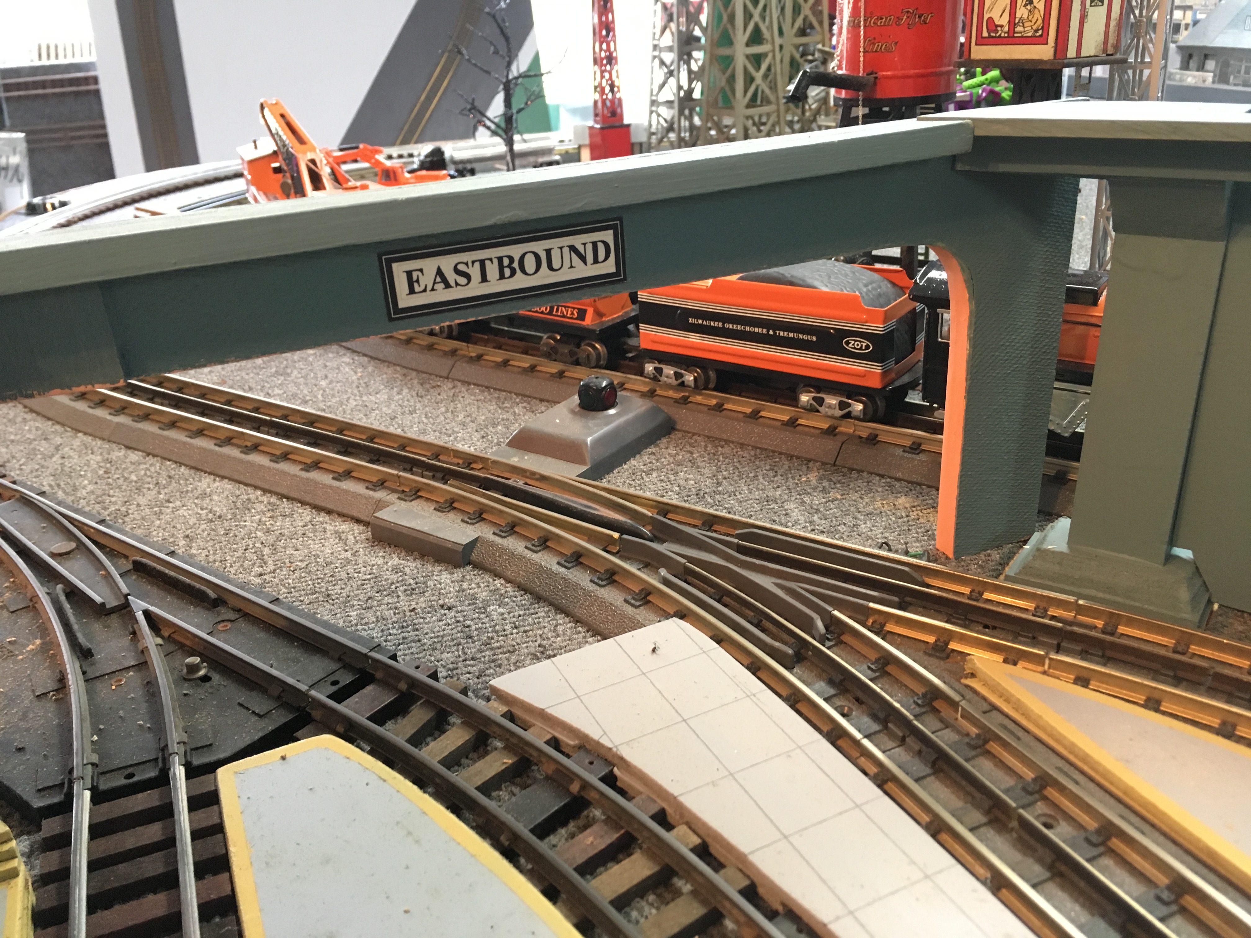
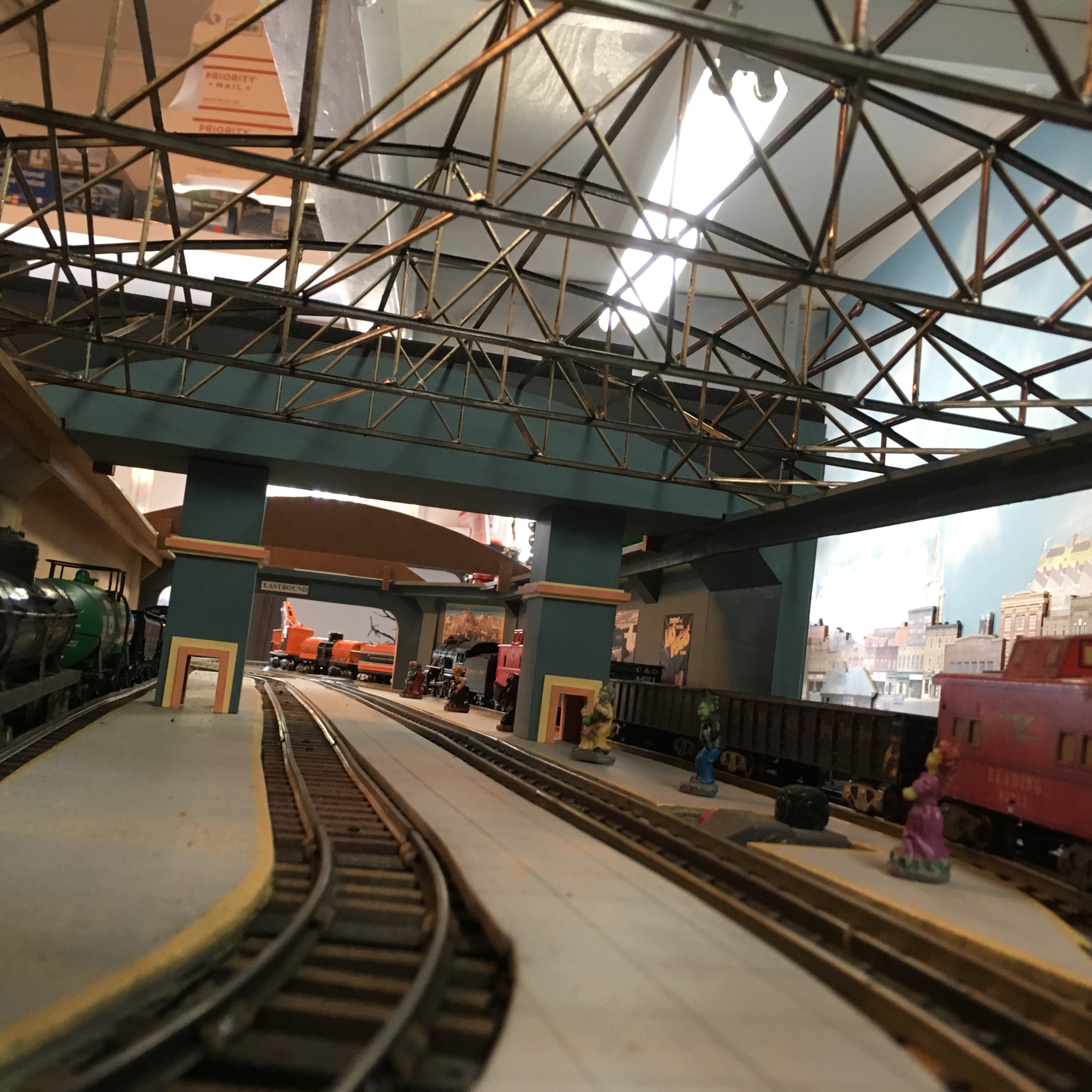
Eastbound Portal
The four tracks inside the terminal squeeze down to become just two tracks through the rest of the layout. That
allows the terminal to nerrow down to match. The narrowing provides some extra interest for the building and for the roof.
|
East End Track Level
Here you can see a trackside view of the interior facing to the far west end of the terminal. The elevator
doors are open on both sides. To the right of this image, you can see where the interior shops and restaurants will be placed. The passengers
on the O-Gauge platform are not exactly to scale and not exactly the sort of people we expect to encounter through most of the year.
|
|

|
|
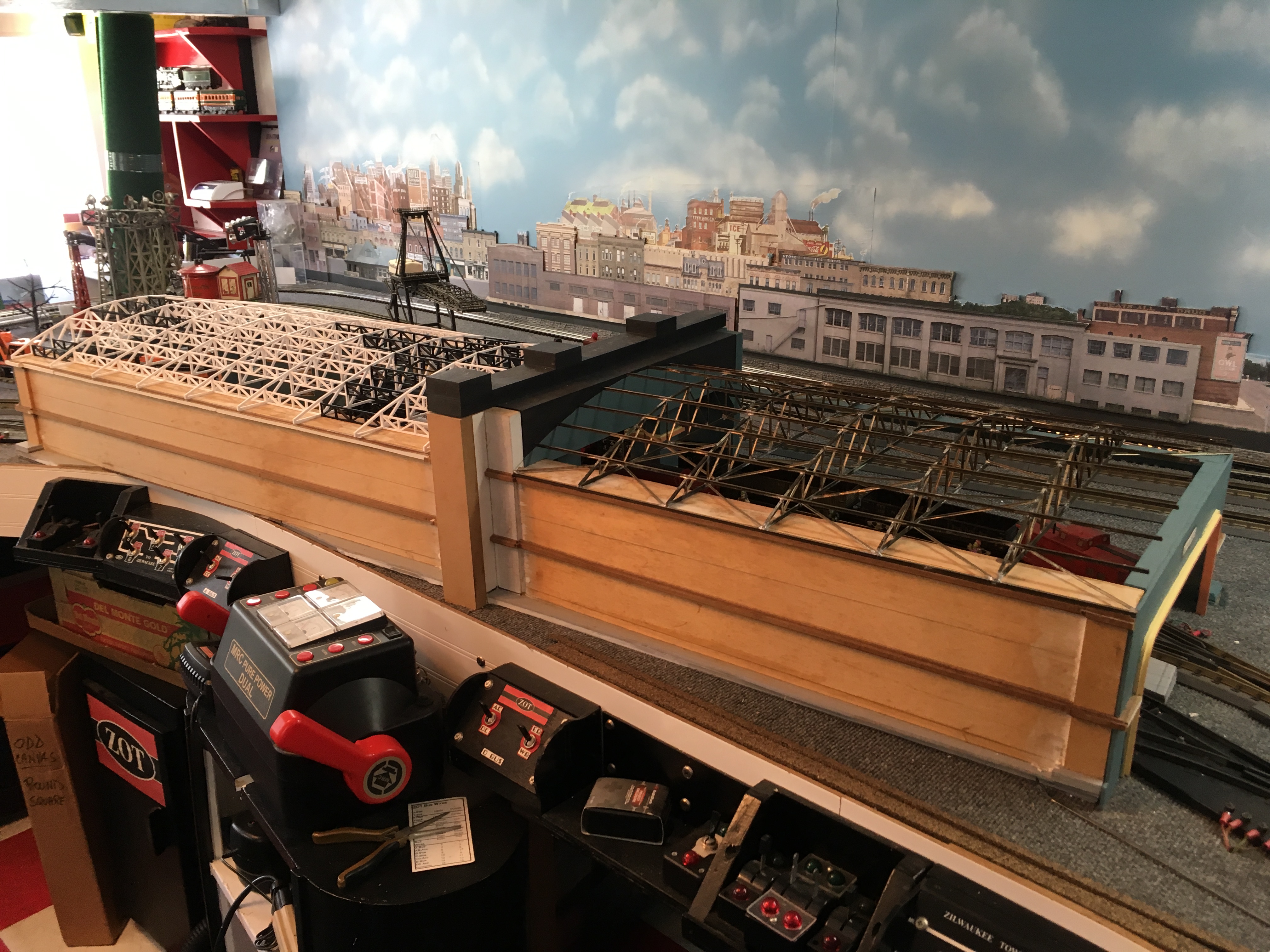
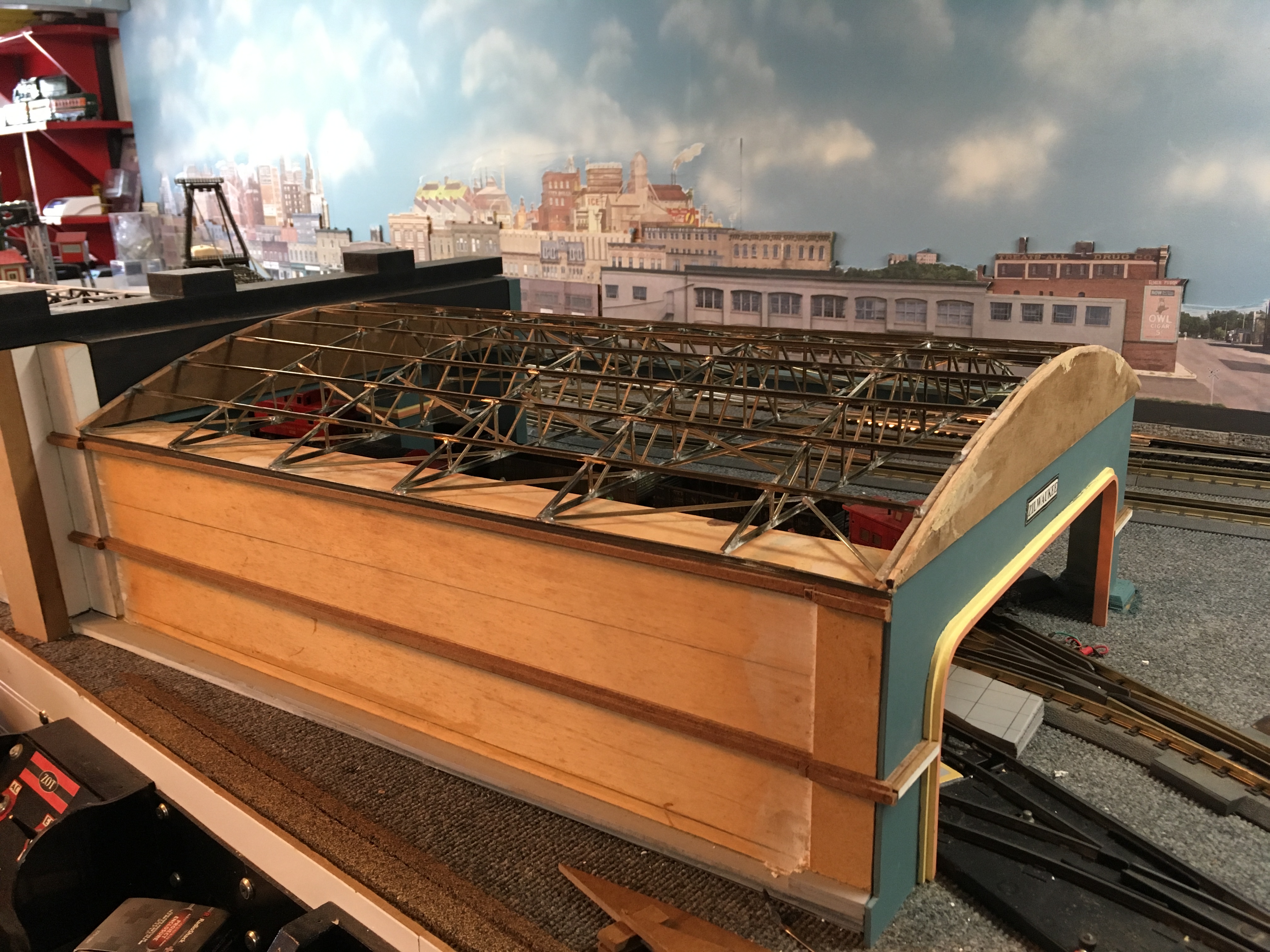
West End Overall
The West end is shorter than the East end and does not become narrow.
|
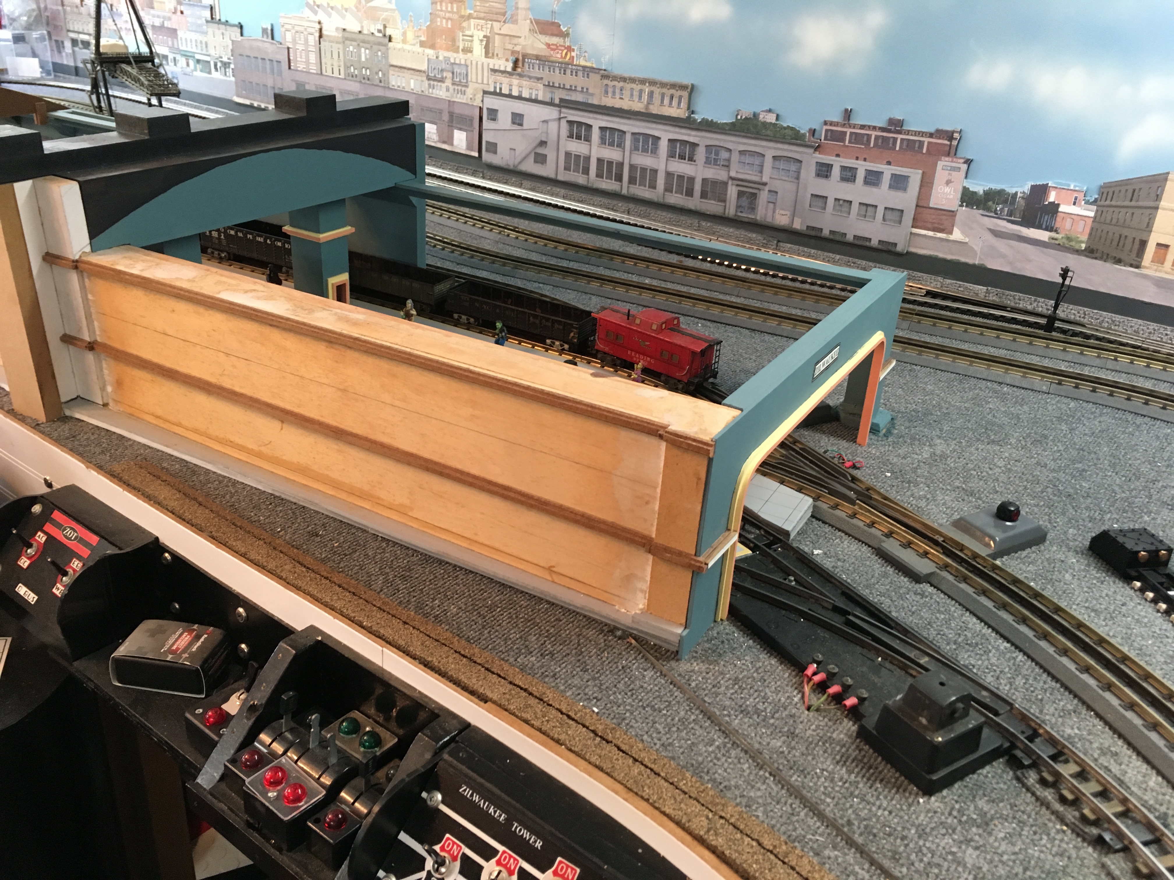
Westbound Track
At the West end, there is an additional switch track leading to a spur siding behind the terminal
building. As you can see, it is O-Gauge track. All 5 of the sidings can be switched off independently. That allows the dispatcher
to store trains and the passengers to board and detrain as needed.
|
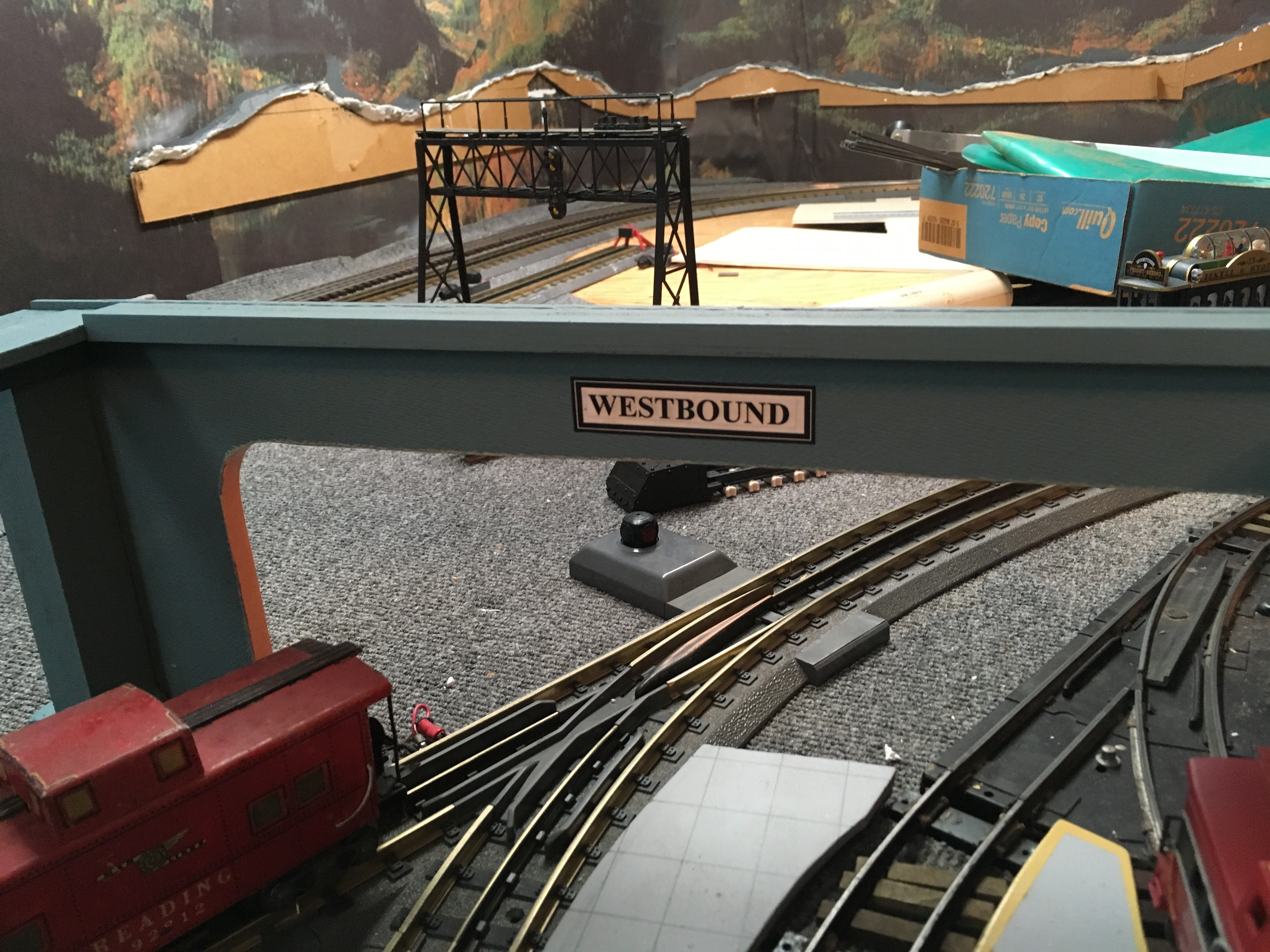
Westbound Portal
When Horace Greely said "Go west, young man", this is the direction he intended.
|
|
West Side Roof |
|
|
|
West End Track Level
American Flyer switch to the laft side and MTH O-Gauge Real Trax switch to the right side as we enter
the west end of the station. There is a second O-Gauge switch just past that caboose. It leads through the opening in the wall and
to a stub siding on the back side of the terminal.
|
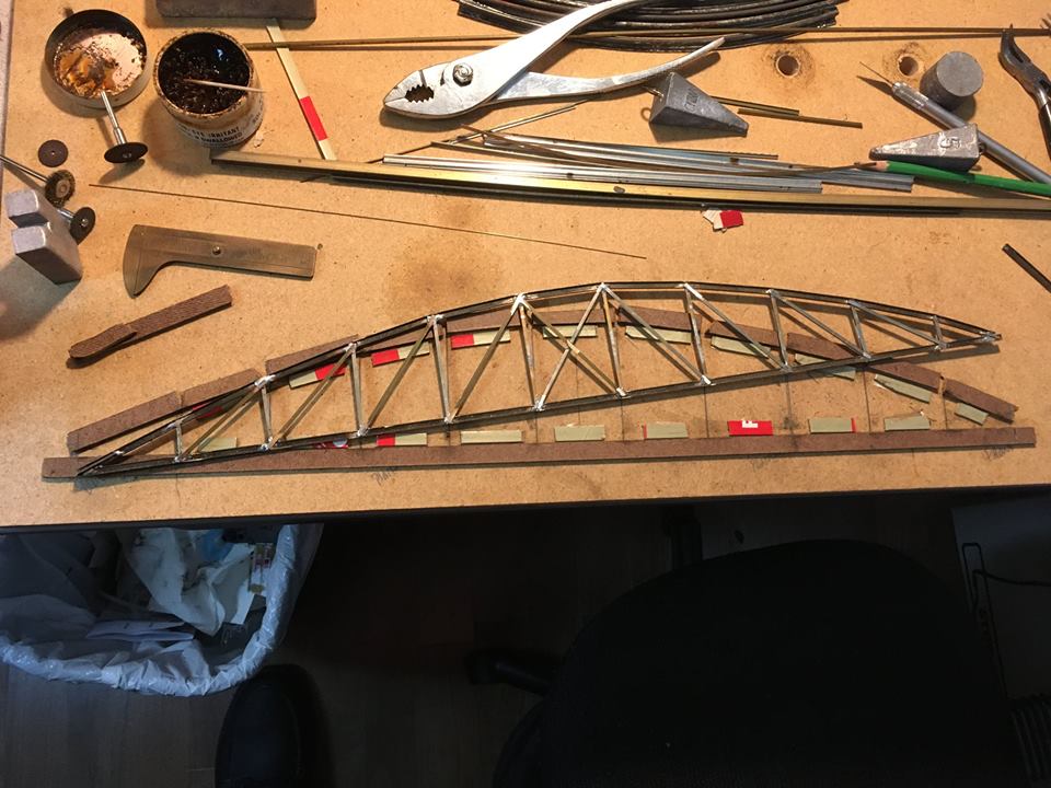
West End Roof Truss Tools
The west end roof is made from metal trusses. I used code 148 brass rail for the outer
outlines (chords) and code 100 rail for the verticals and diagonals. The material is readily available by salvaging old track found
cheap at train shows. Each piece is cut to fit and soldered to the rest.
|
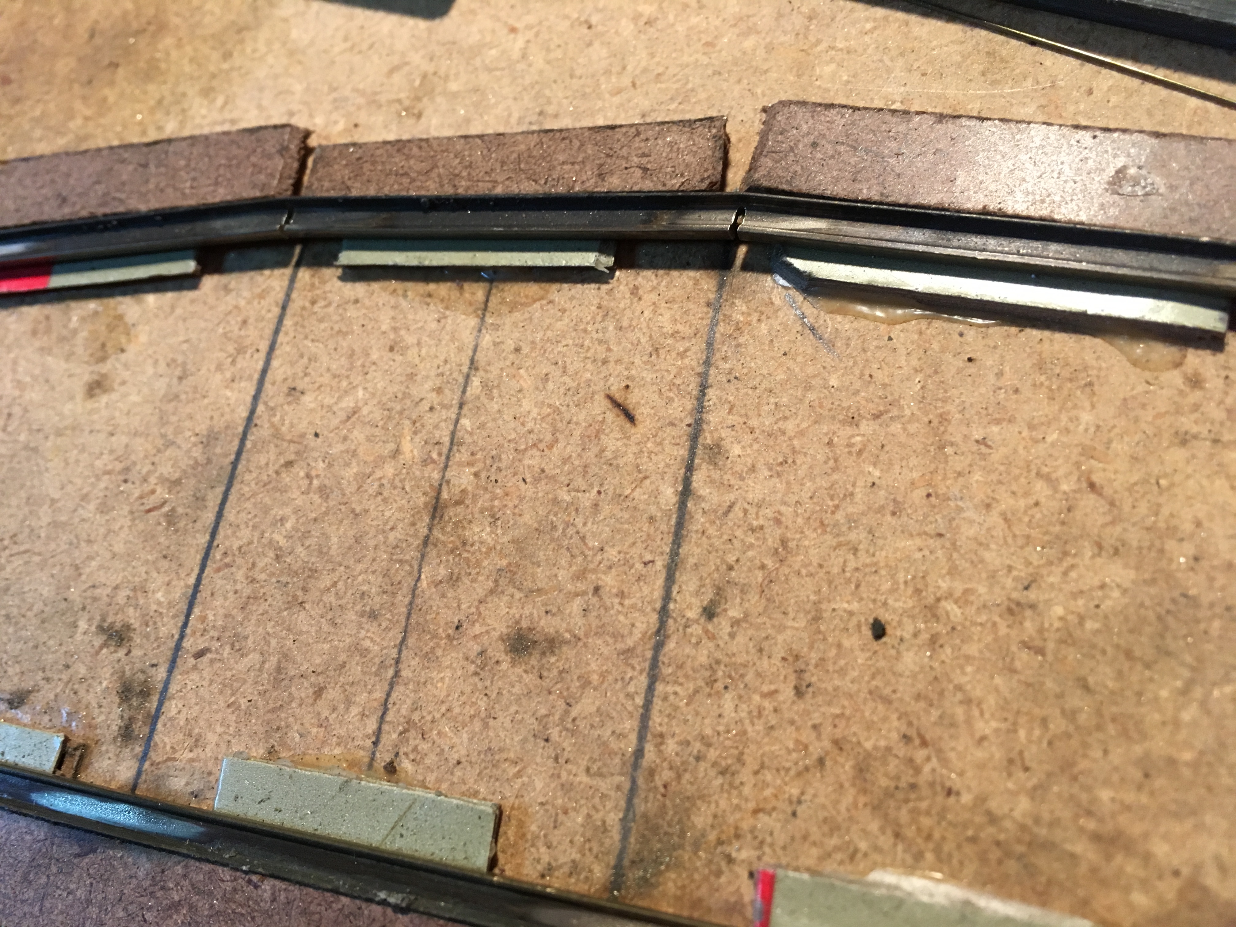
Soldering Jig
The parts are held in place during soldering with this jig. The base is particle board. The outer
limits are made from Masonite. The inner alignment pieces are made from cardboard. Enough thicknesses of the cardboard are
laminated to the proper thickness to allow the bottom flange to rest on the base and the rail head to rest on the cardboard.
That allows the bottom of the rail pieces to be vertical when laid on their sides.
|
|
|
|
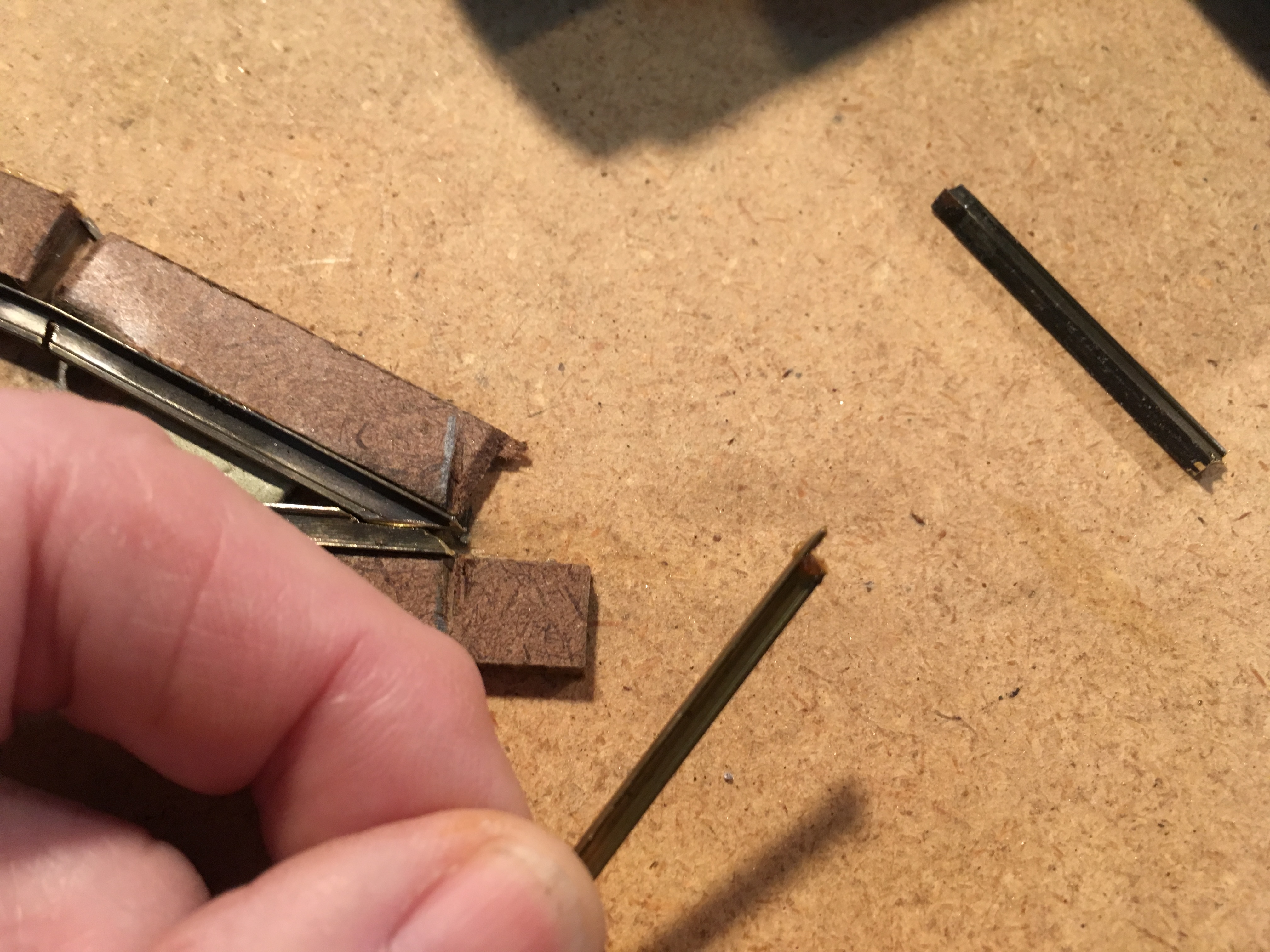
Vertical Support
The verticals and diagonals are cut to length and then shaped using a Dremel tool. The flat part
overlaps the outside chord pieces to make a stronger joint.
|
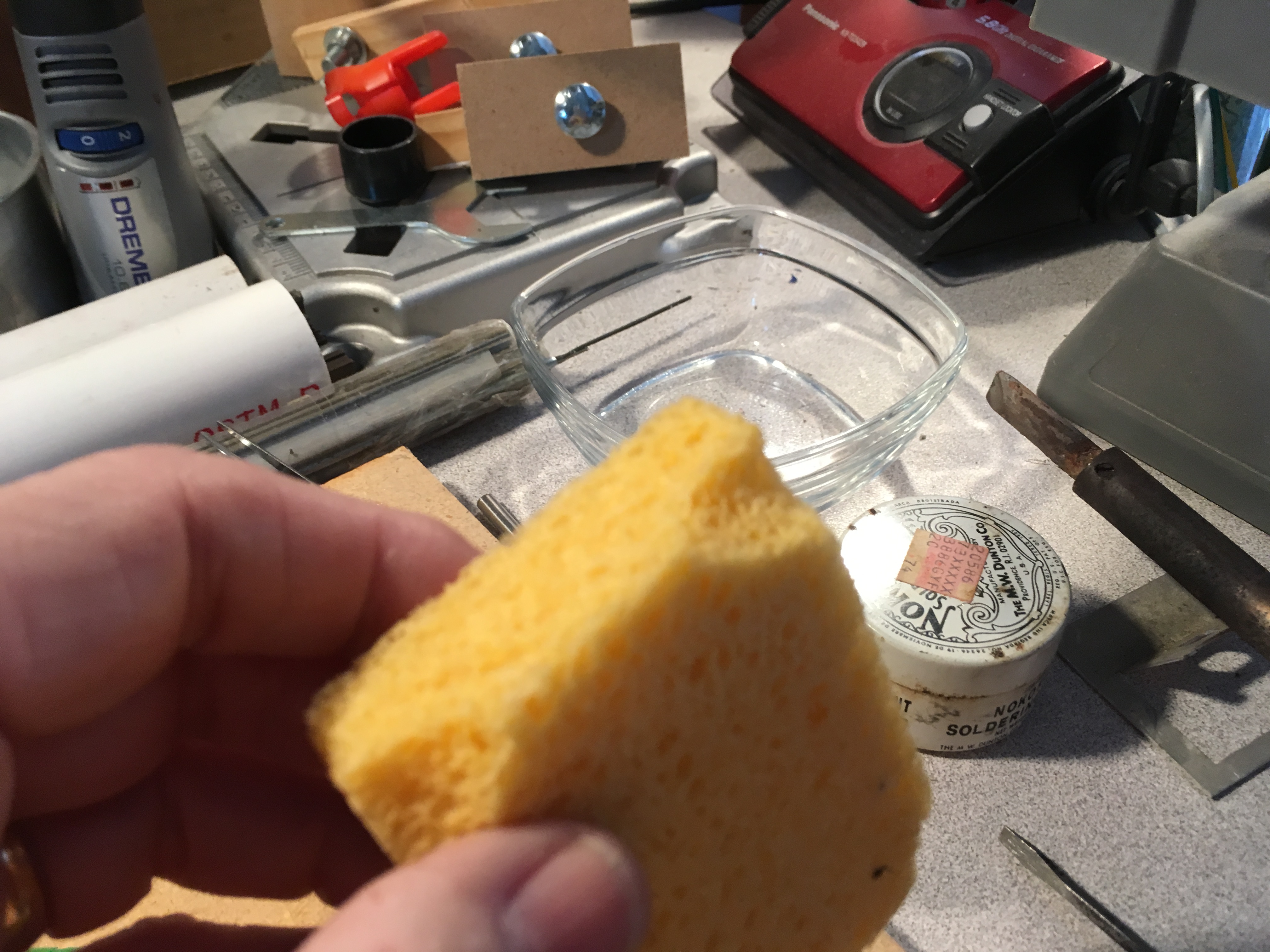
Sponge
I cut a piece of sponge to fit a glass bowl. The wet sponge is used to wipe the hot soldering iron
and keep it clean. Enough heat is essential when soldering. Cleanliness makes for better heat conduction.
|
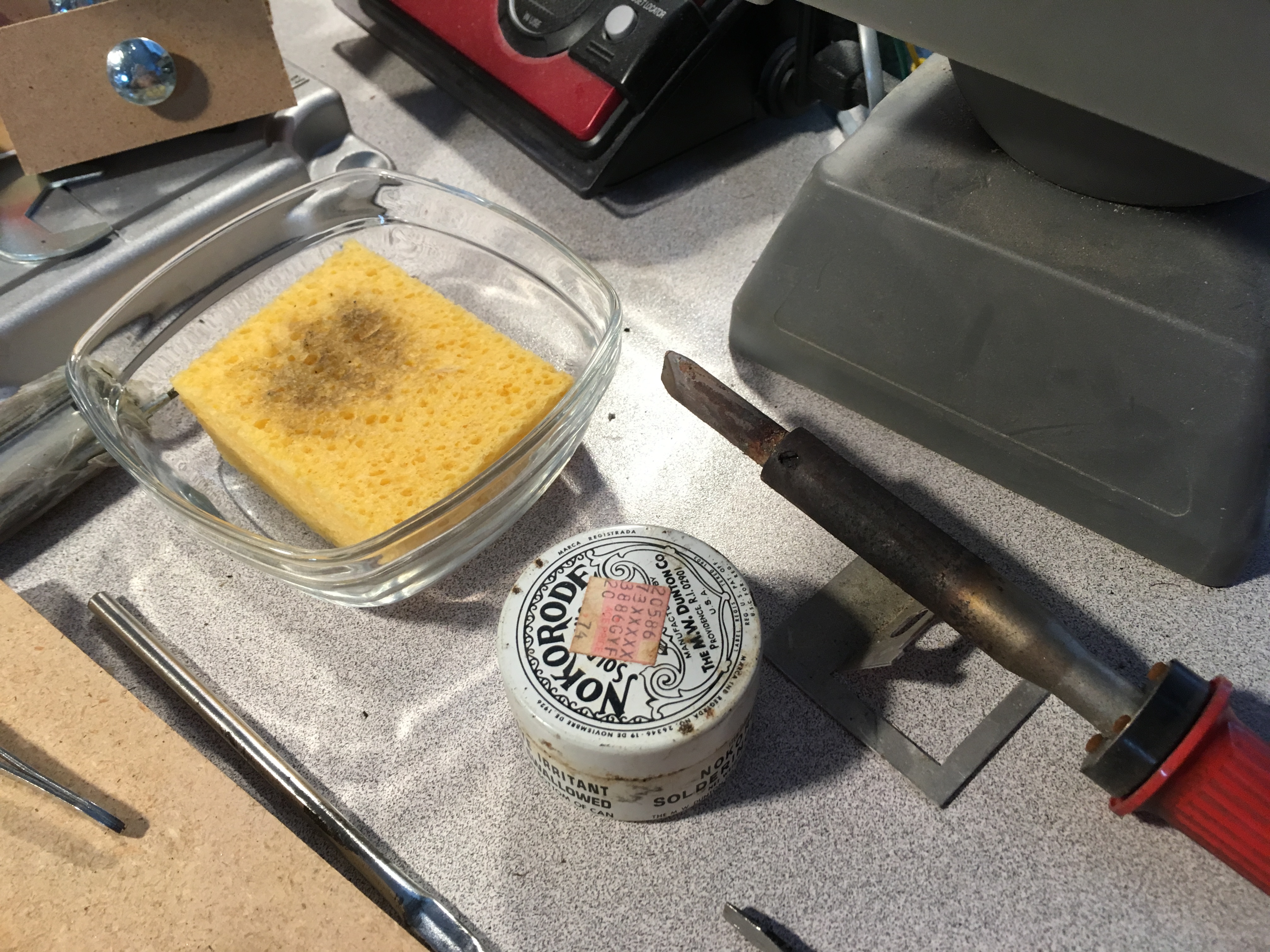
Soldering Tools
Here is the iron, the bowl for the damp sponge and the tin of soldering flux. Flux keeps the metal parts
clean as the solder melts. It also aids in conducting heat. Get the joint hot as fast as possible, apply the solder and release.
|
|
|
|
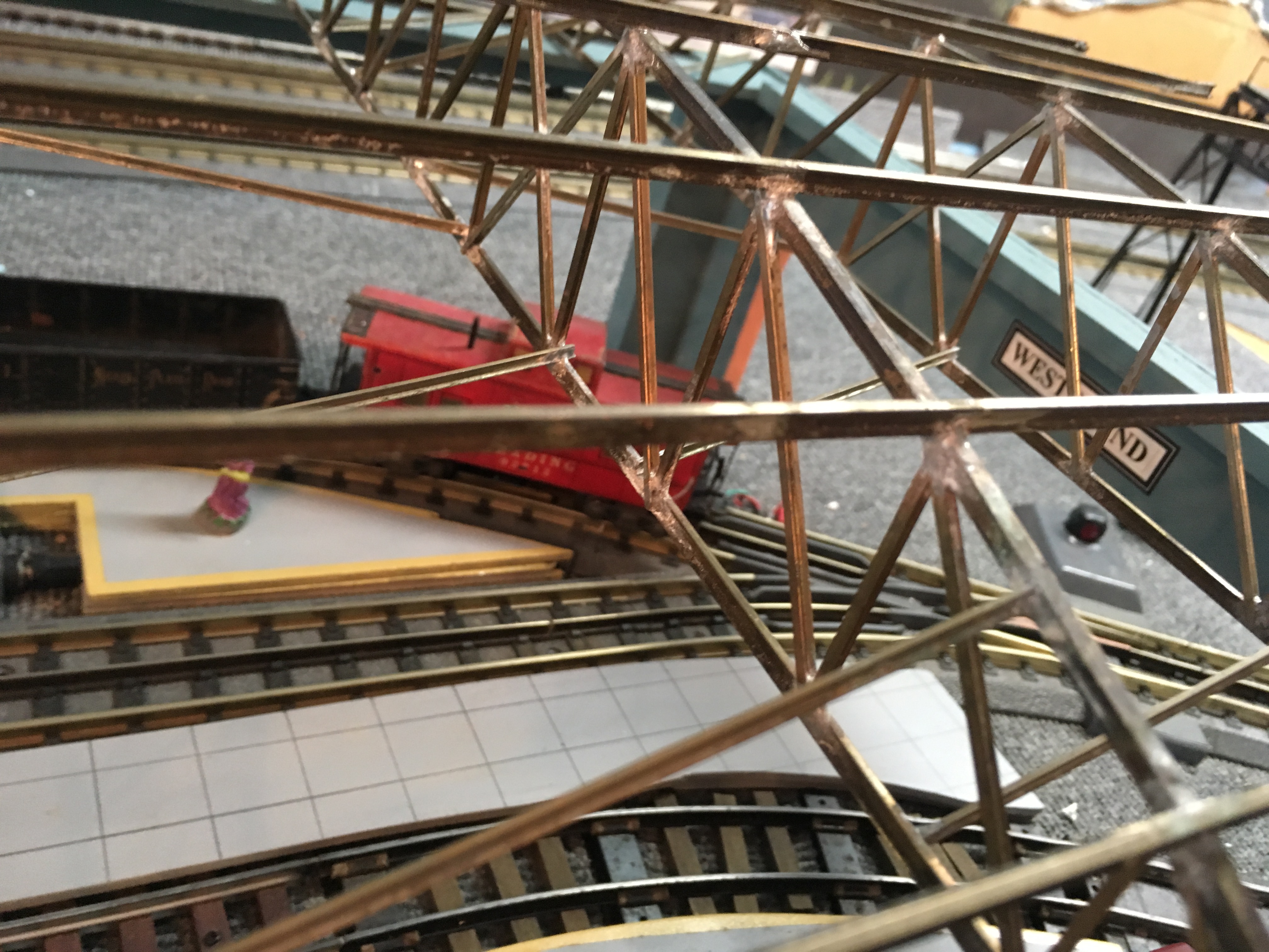
Truss Joint
Once the trusses are fabricated, they need to be joined with others and braced. In the real world, we might
expect gusset plates to reinforce the joints. Not needed in this case. The joints are pretty strong due to the overlap. Also, the
gusset plates would be hard to see once the glazing is applied.
|
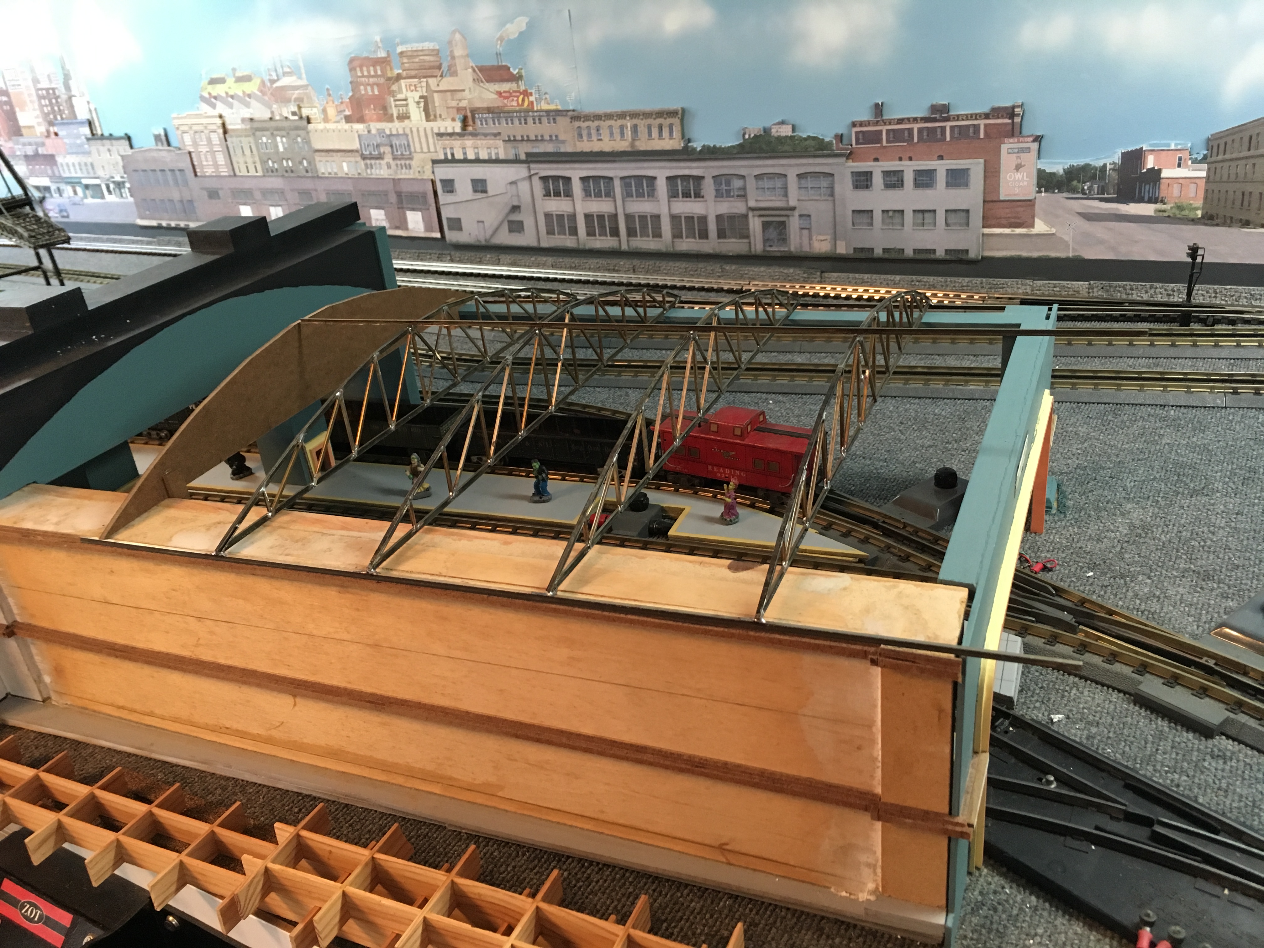
Trial Fitting
A trial fitting of the first four trusses. They are soldered to the longitudinal parts (more code 148 rail)
and braced with some code 100 pieces at a variety of 3D angles. This view includes one of the profile pieces made from Masonite.
|
West End Metal
The design calls for 5 trusses on the west end roof. The corresponding end pieces are to be made from
Masonite. In fact, the original profile pieces are drafted to serve as the solid ends of the roof.
|
|
|
|
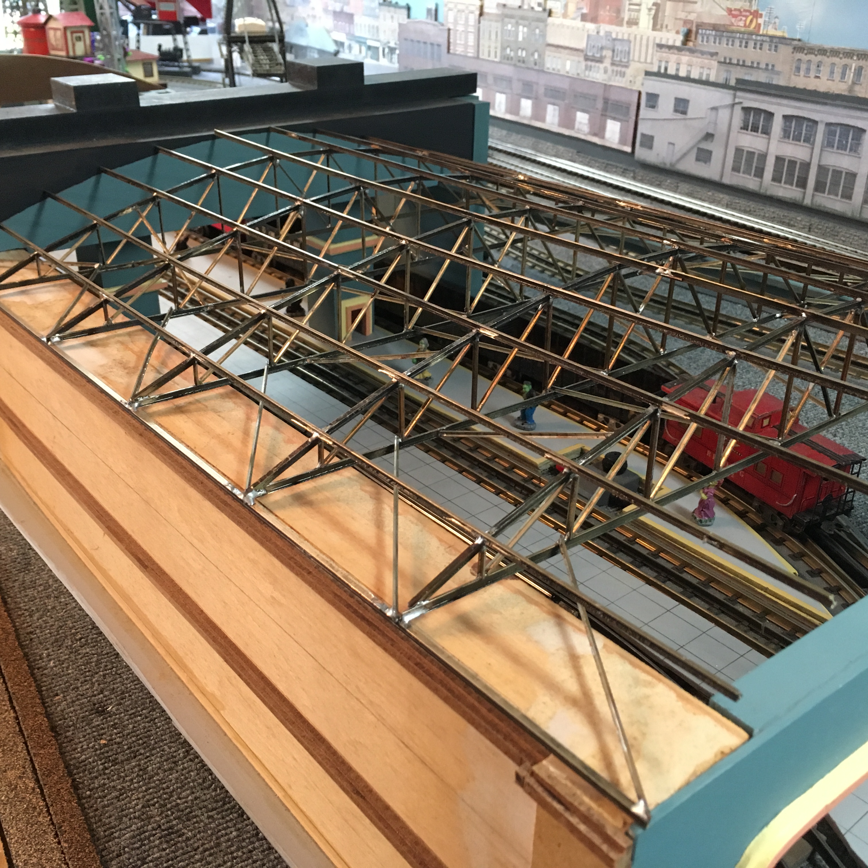
View From Inside
The passenger-level view shows what I had hoped it would. The details of the trusses add depth and a realistic feel.
|
Test Fitting Metal
A final test fitting of the metal parts shows the snug fit of the roof truss assembly over the tracks at the west end.
|
Solid End Pieces
The metal roof assembly is heavy for a model building. It is necessary to mount the solid end pieces
securely. Cannot solder to Masonite. So, the hard board was attached to the metal using J B Weld epoxy and some additional bracing with oak strips.
|
|
East Side Roof |
|
|
|
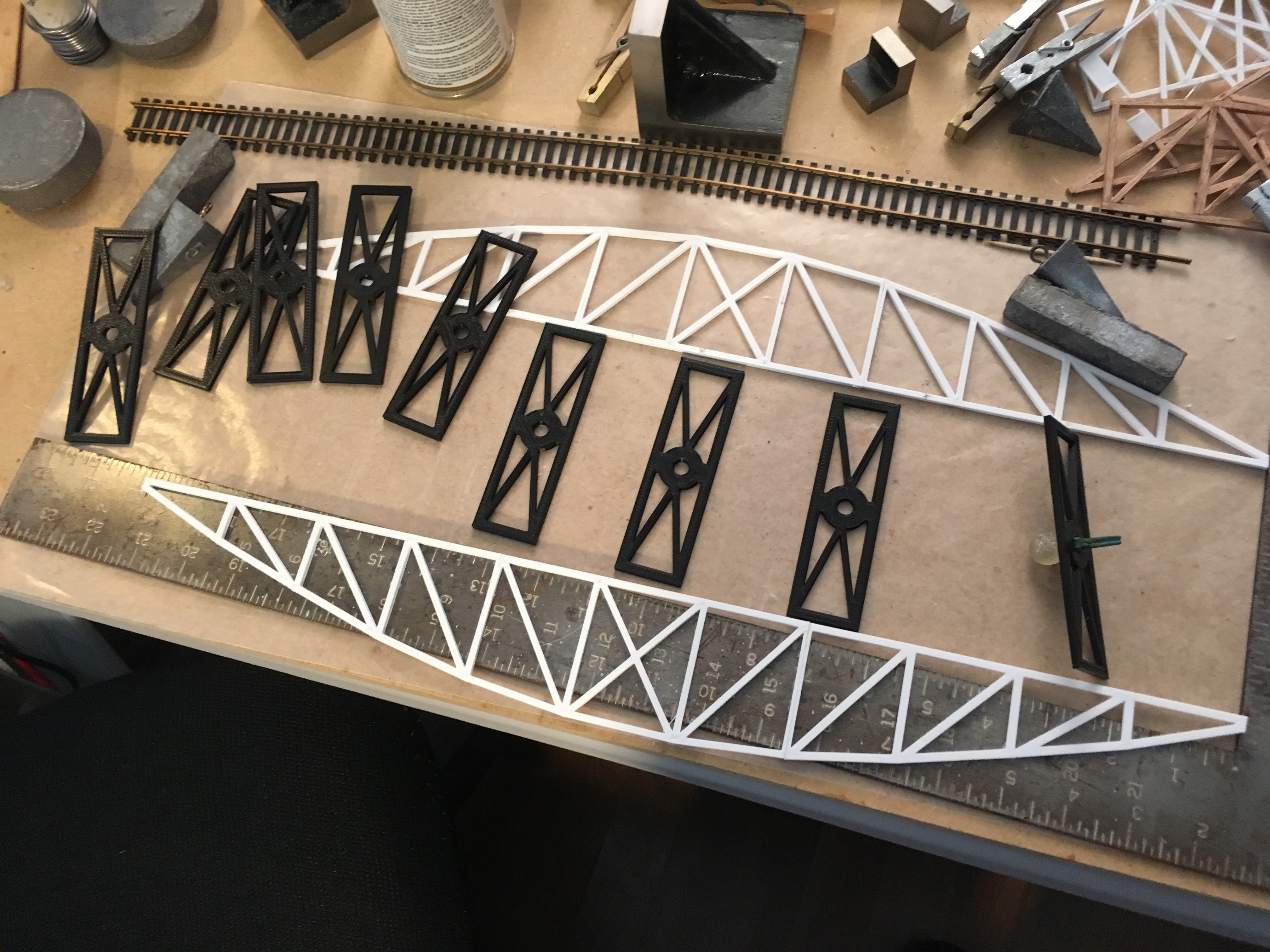
Plastic Roof Trusses
Cutting and soldering all of that metal for the west end was tedius and time consuming. I used a different approach on the east end.
I designed roof truss parts using SketchUp. Then, exported those as STL files and printed them with a Dremel 3D20 printer. It uses PLA plastic
filament. It took a little while to learn SketchUp and to get the settings right on the printer. One consideration for my process is that the printer
cannot print in space. That is, anything that is printed must be supported from underneath. There are limits to how much overhang will work properly.
Since I had already assembled the metal trusses using mostly flat parts, it was natural to use that knowledge for this approach. The trusses were printed in
three sections: the center and the two ends. The supports for lighting were also flat parts.
|
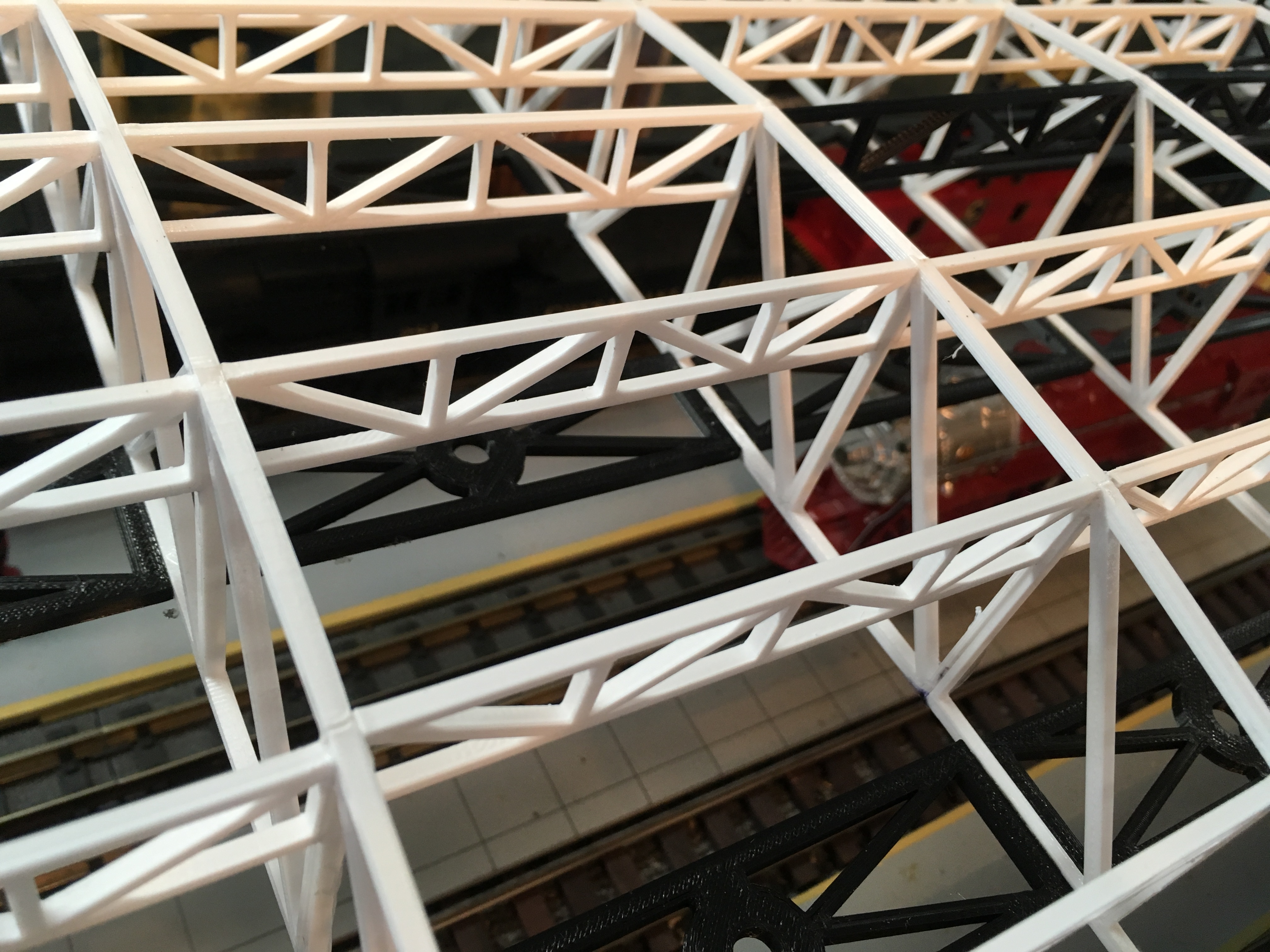
Longitudinal Trusses
These parts connected each of the trusses to their neighbors. They align with the top chords.
|
Assembled PLA Trusses
The only plastic filament that my printer will use is PLA. That plastic is reasonably strong and rugged. Here you can see a pile of assembled
trusses ready for roof fabrication.
|
|
|
|
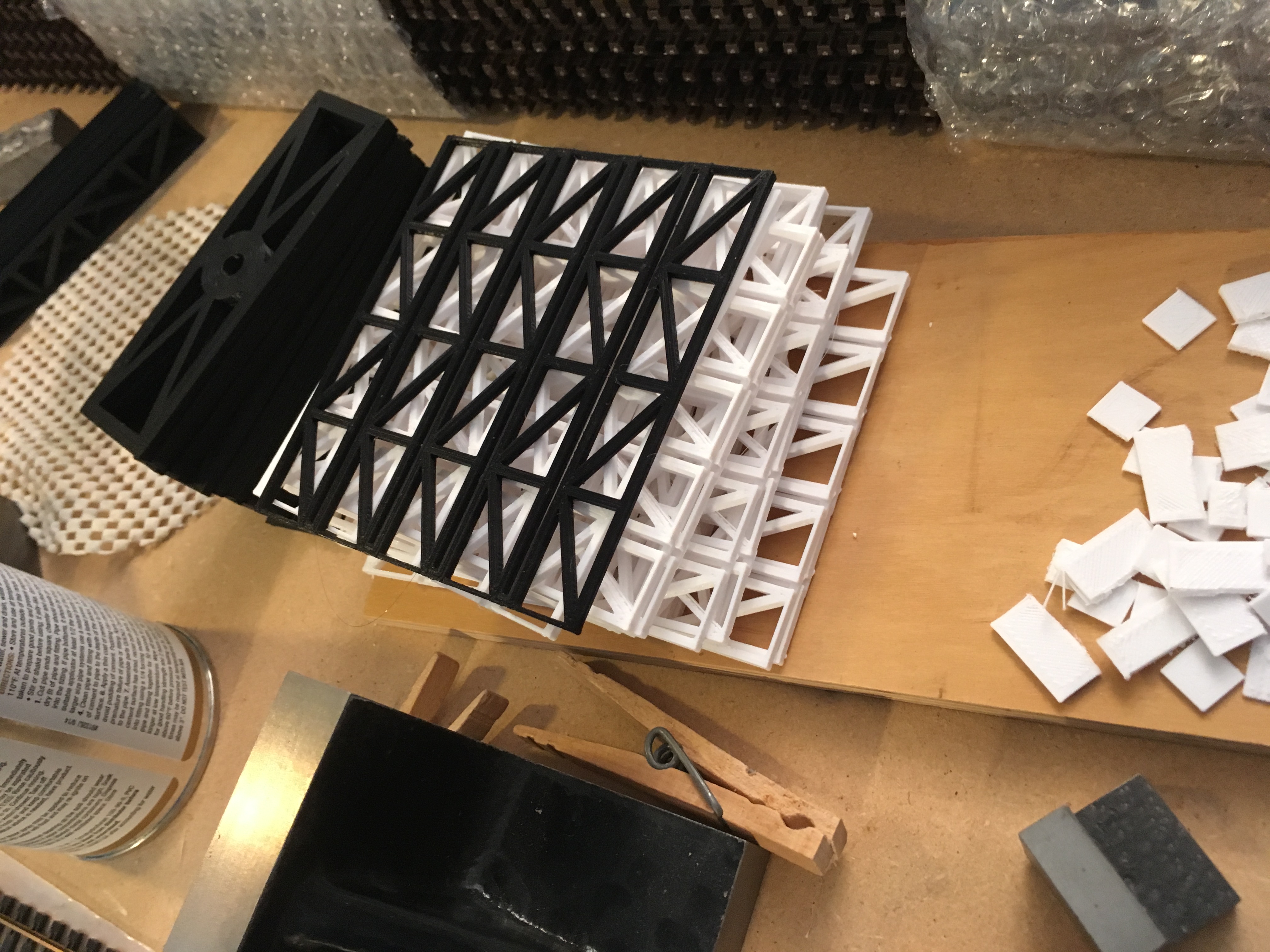
Starting to Assemble
Each truss is made from three pieces. The center pieces are common to all trusses. Each
truss has two end pieces. Those ends are symmetric for each truss. Seven of the assembled trusses are full-width. At the
east end, there are two trusses that are each a little narrower. The steel blocks hold the truss vertically to the
assembly surface. It is covered in waxed paper. Lead fishing weights hold the bottom (light fixture) pieces in place
while the cement dries.
|
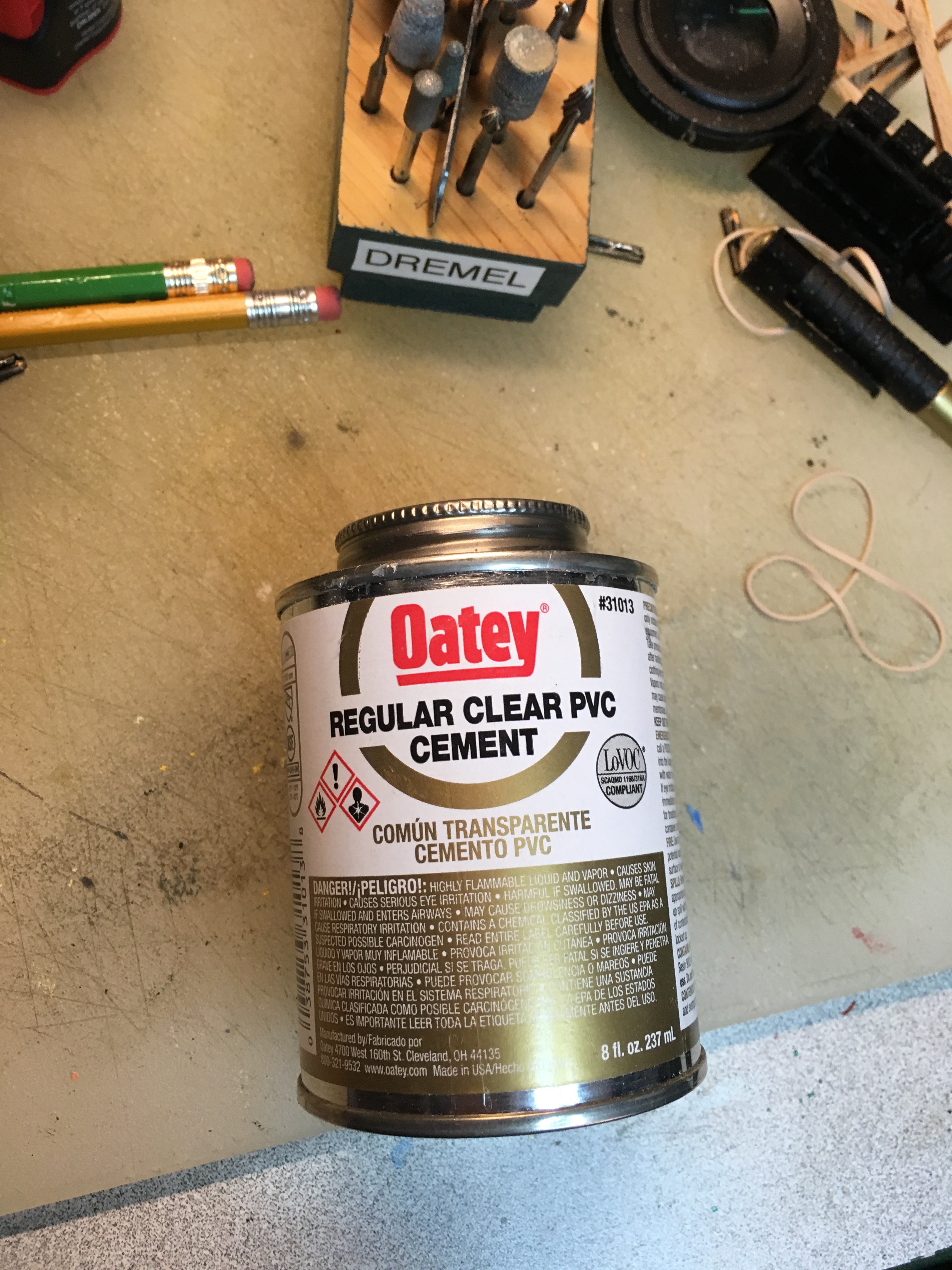
Cement for PLA
The very handy PVC pipe cement works very well. I buy it at the local hardware store. First,
scuff the surfaces to be joined with fine sandpaper. Next apply the cement to both of the mating surfaces. Finally,
clamp them together using the steel blocks (Micro-Mark) and lead weights. Let dry a few hours and proceed to the next joint.
There are three strips of these lower, light-fixture parts. They are placed to be above the passenger platforms.
|
Longitudinal Trusses
One of these longitudinal trusses is glued in place at each of the vertical members of
the turss assemblies. The glue process is similar to that used for the bottom pieces. In this case, I used brass bar clamps
to hold the joints together while the cement dries.
|

|
|
|
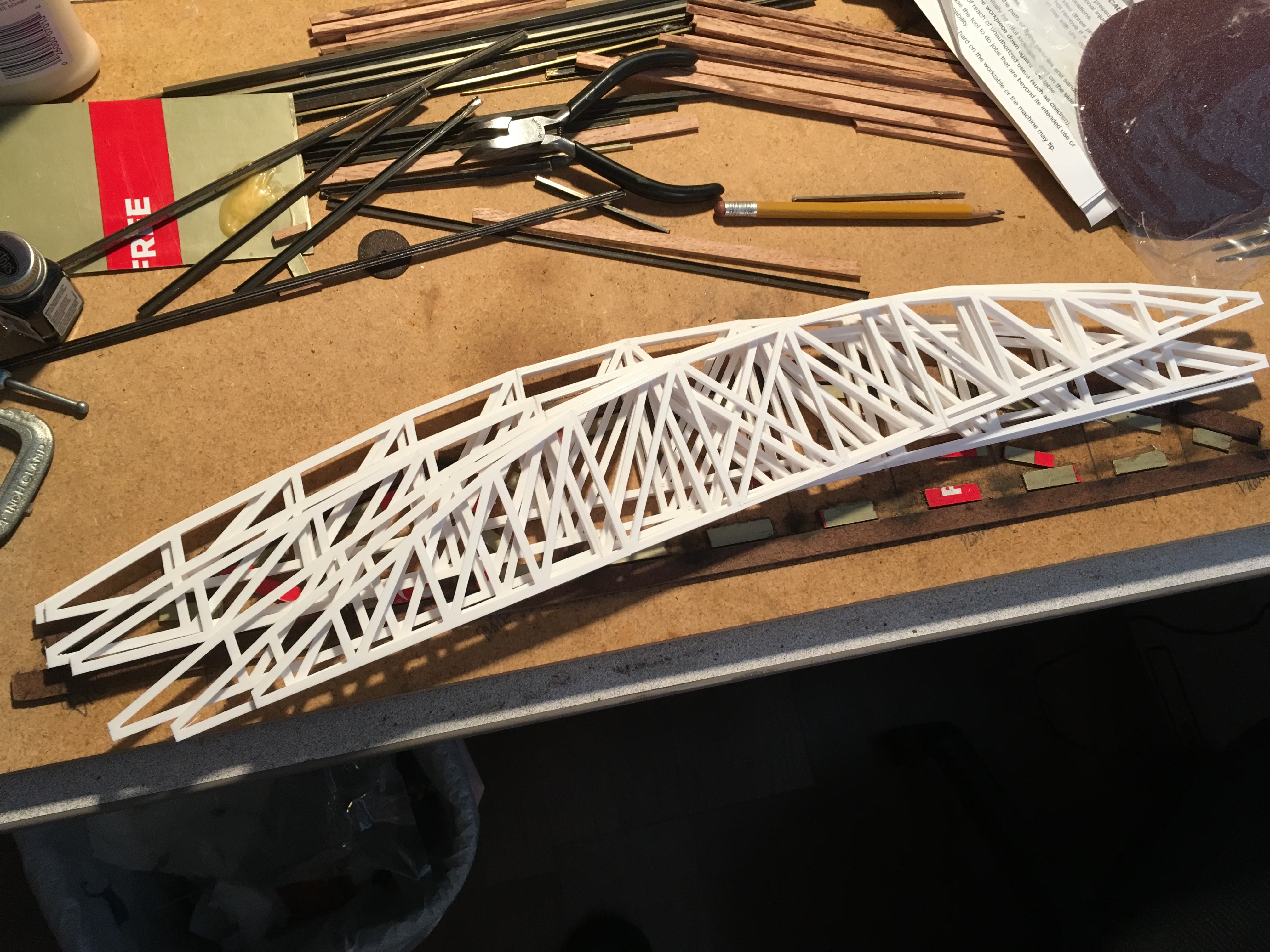
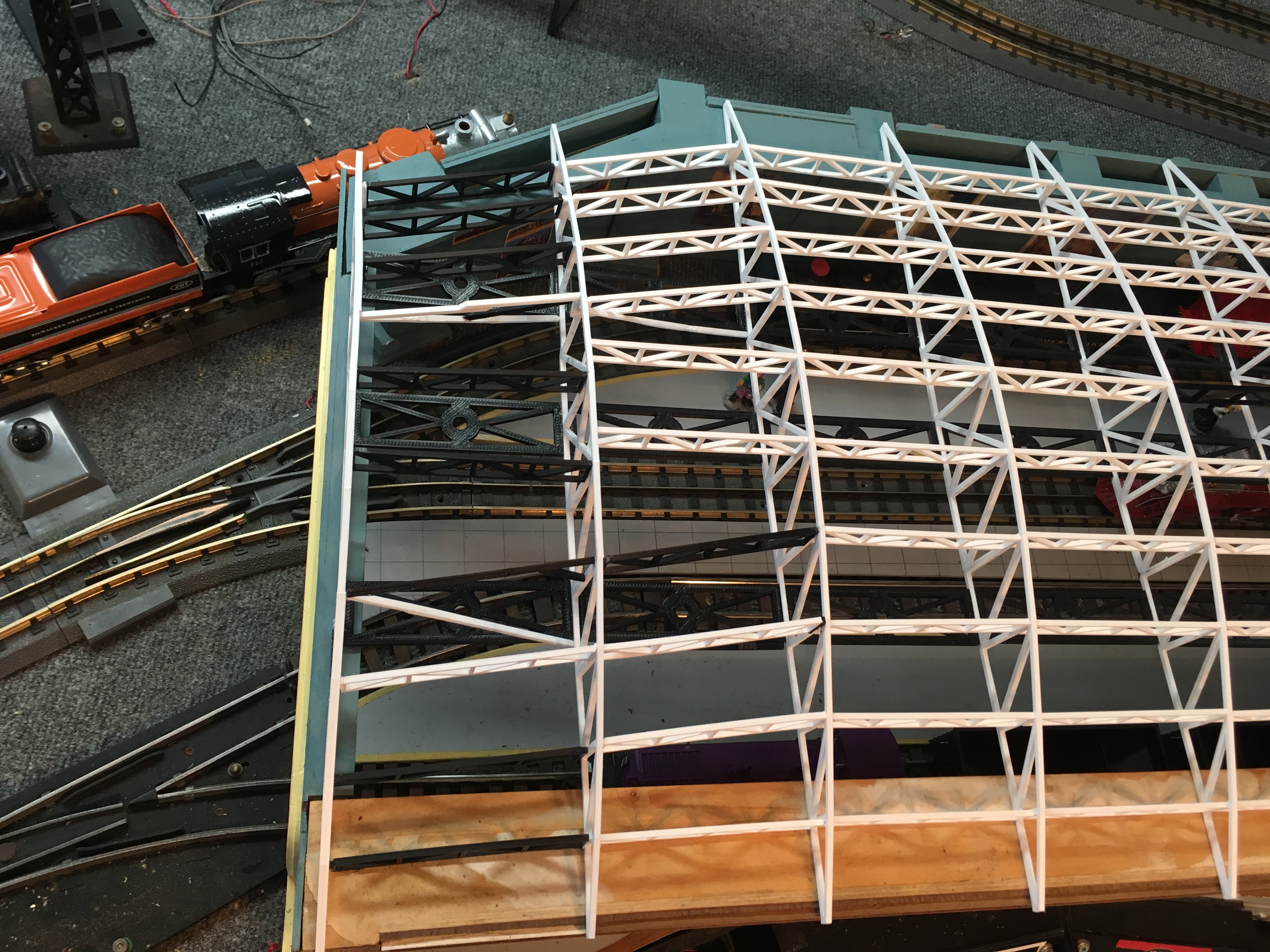
Test Fitting
The seven full-width trusses are joined with the 2 shorter ones. The idea is to keep the lighting
supports in a straight line above the platforms.
|
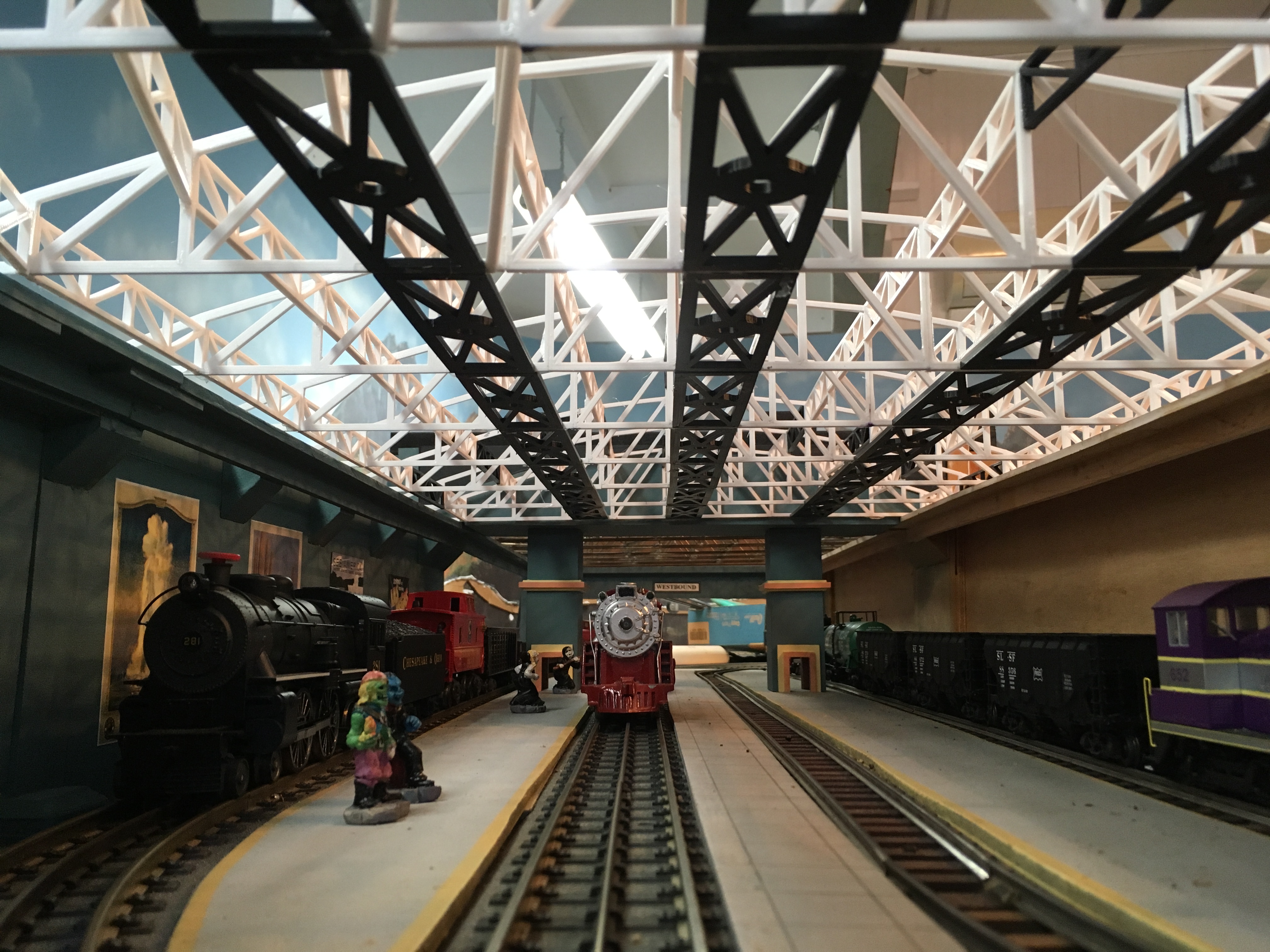
Inside View
Here is the view a tall person would have if they were standing on the tracks. Maybe it is a normal-size
person standing on a photographic platform. My notes from that event are not complete.
|
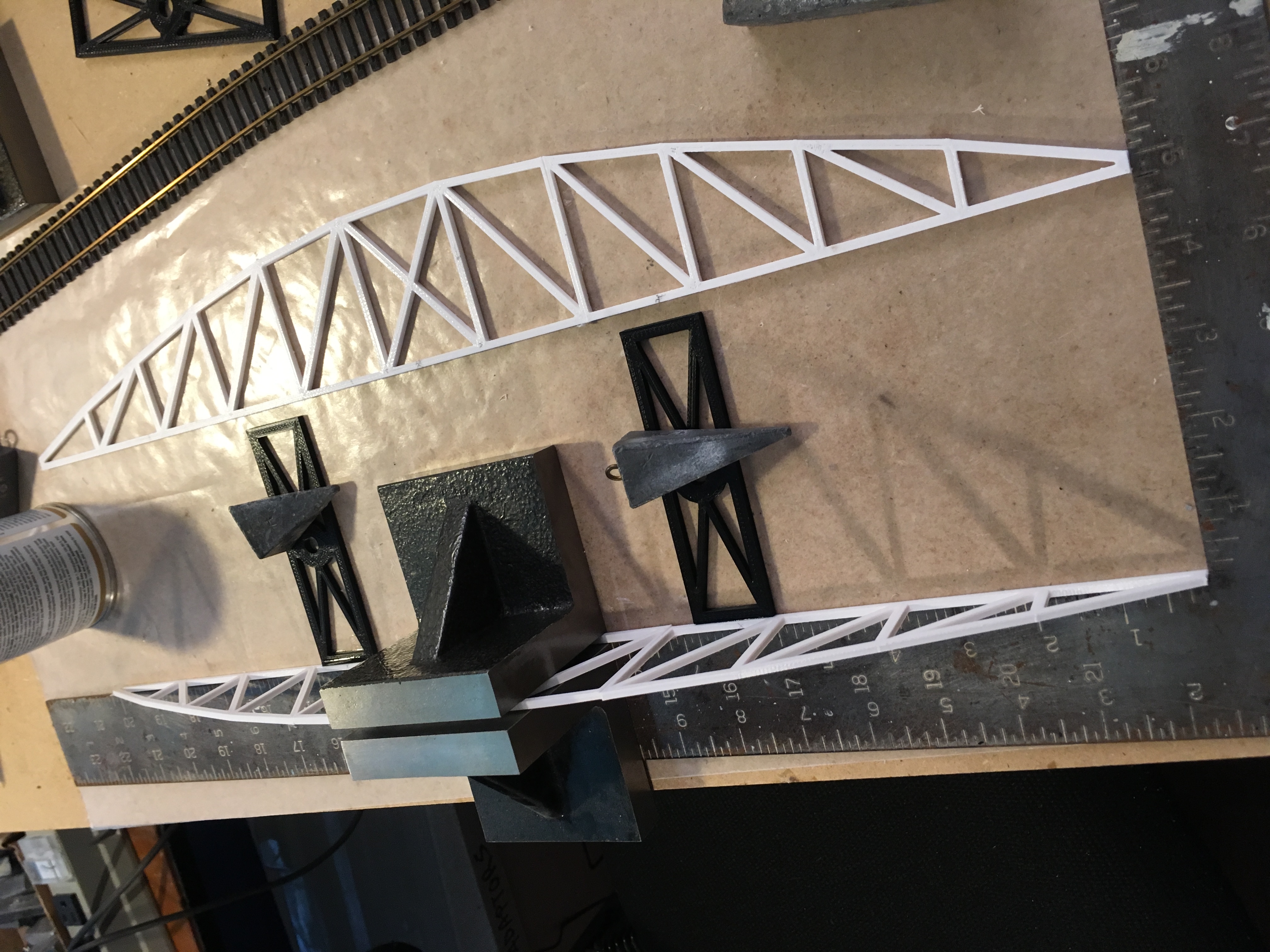
Narrow Trusses
As the tracks depart the station, they merge from 4 to 2 paths. That required some challenging
geometry for the braces. Should look interesting when it gts painted and later glazed.
|
|
|
|
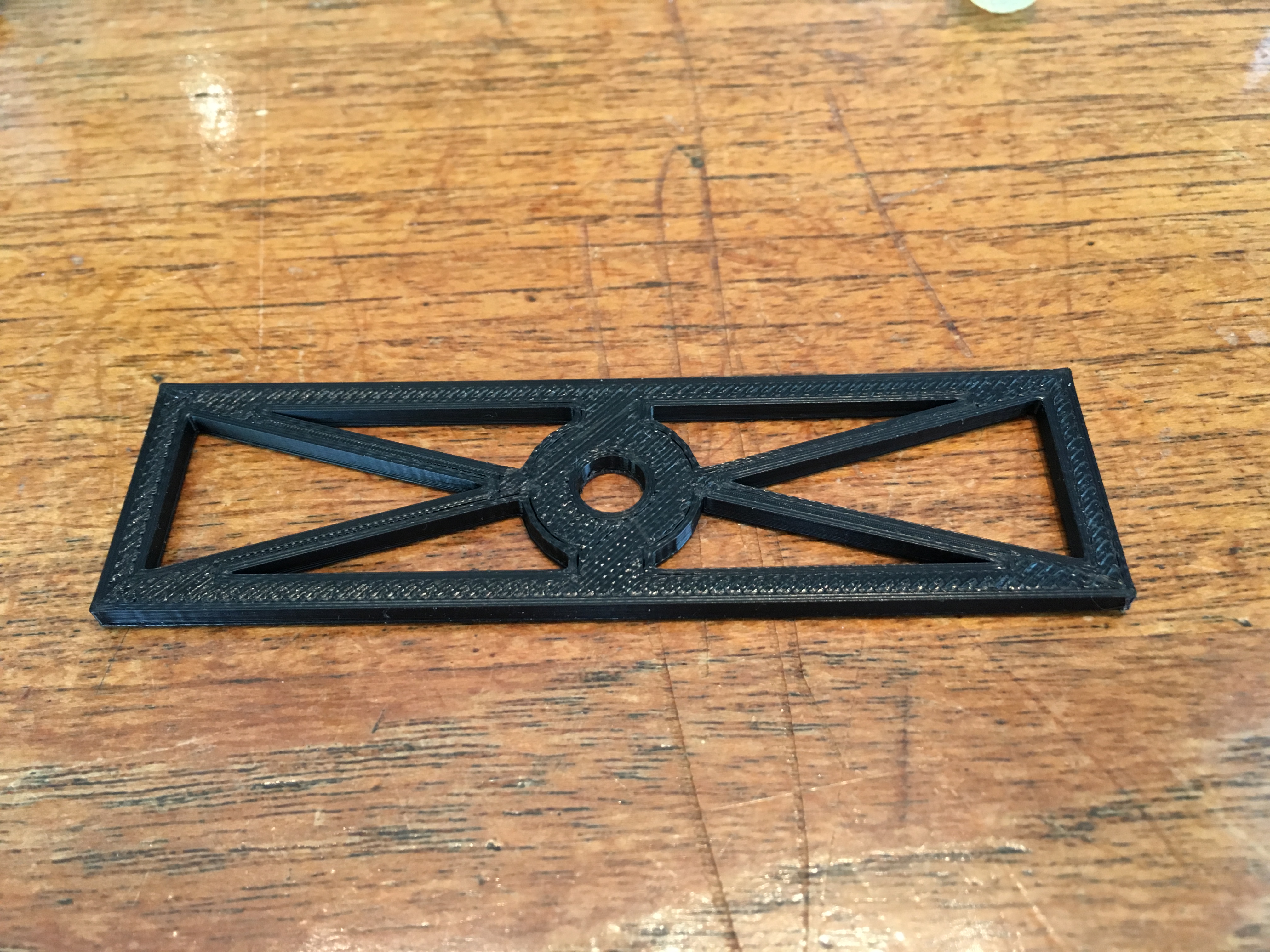
Lower Brace - Light Support
I designed these parts using SketchUp and printed them on my Dremel 3D printer in PLA.
I measured and fiddled until the hole in the center was just right for the sockets.
|
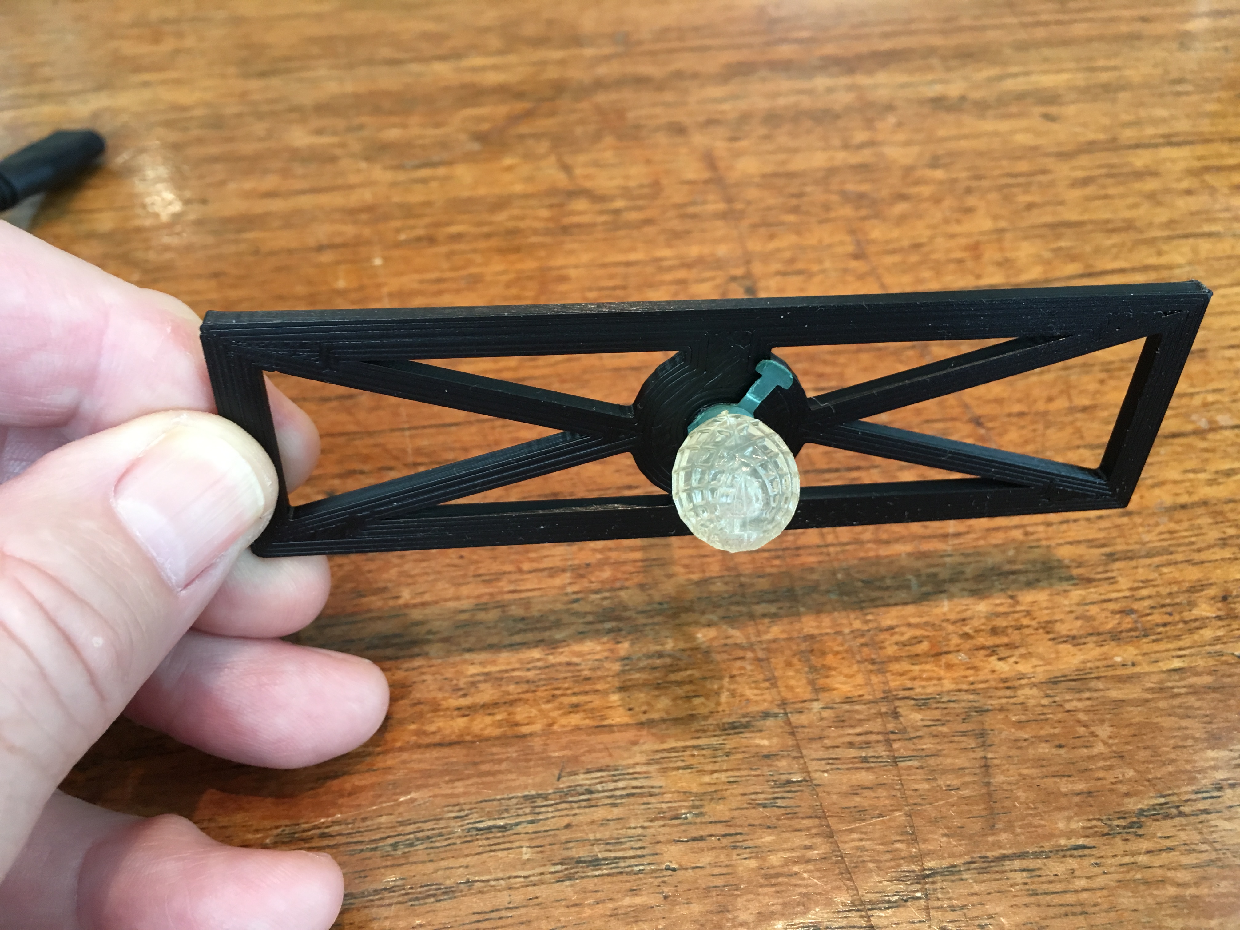
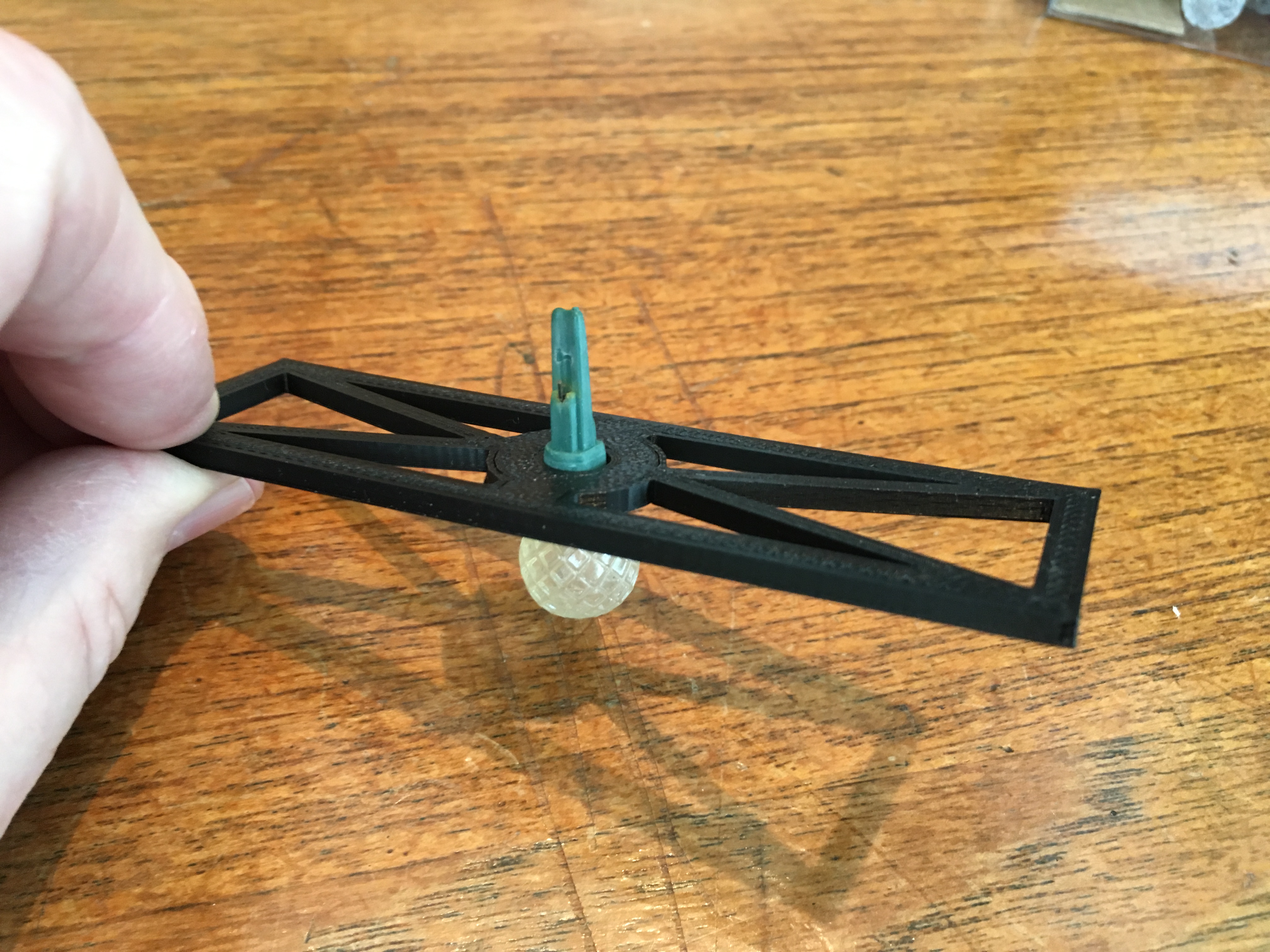
Test Fitting Light Socket
My plan is to use these LED Christmas lights for platform illumination. Every time I have
directly soldered light bulbs into a structure, I later had to replace some and it was troublesome. This time, I am using
sockets. Should make maintenance easier.
|
Top View
This is the view we will see through the clear roof.
|
|
|
|
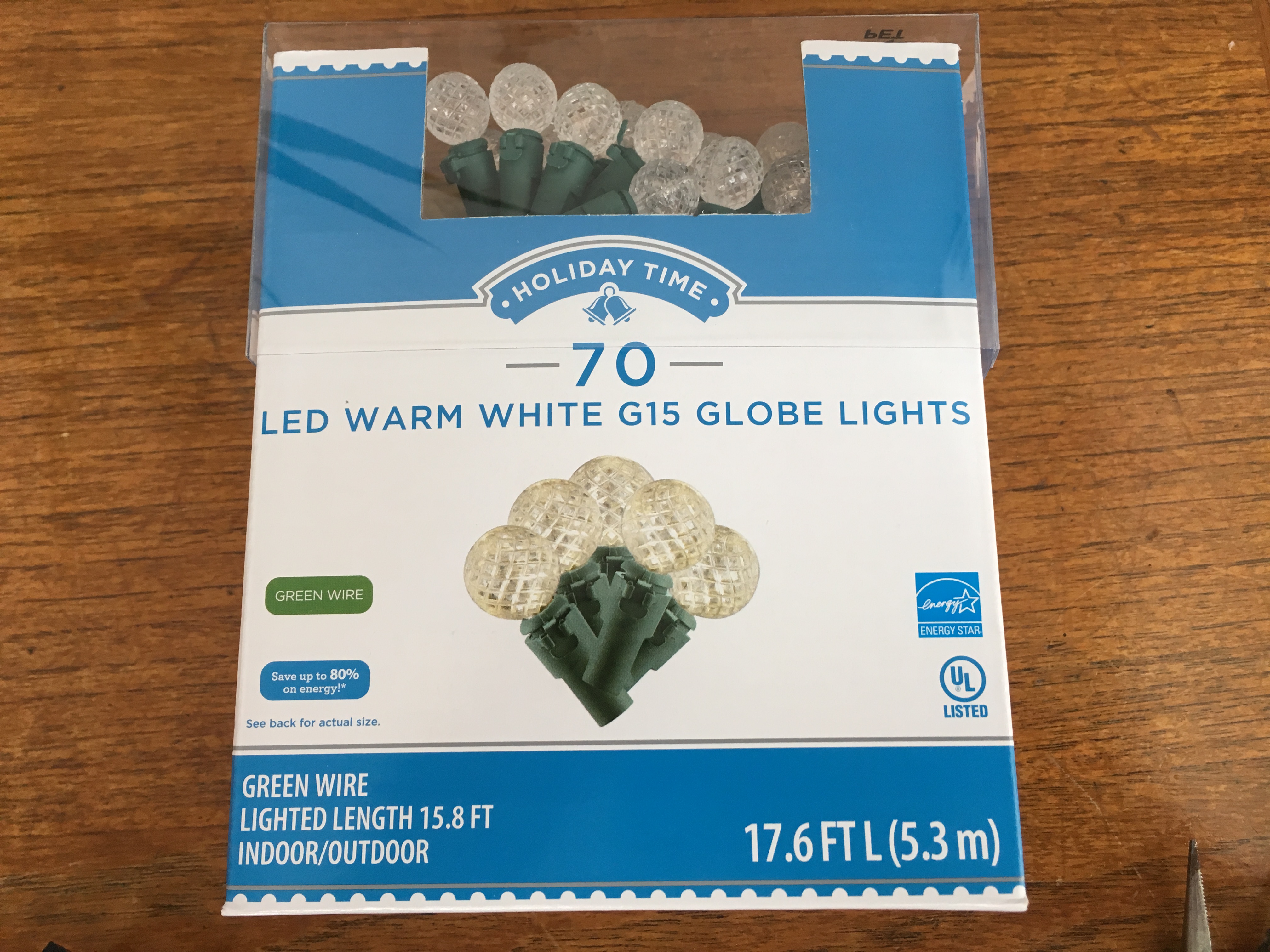
Light Bulb Source
Found these strings at WalMart. At my store, this year they come out to about 7 cents each.
|
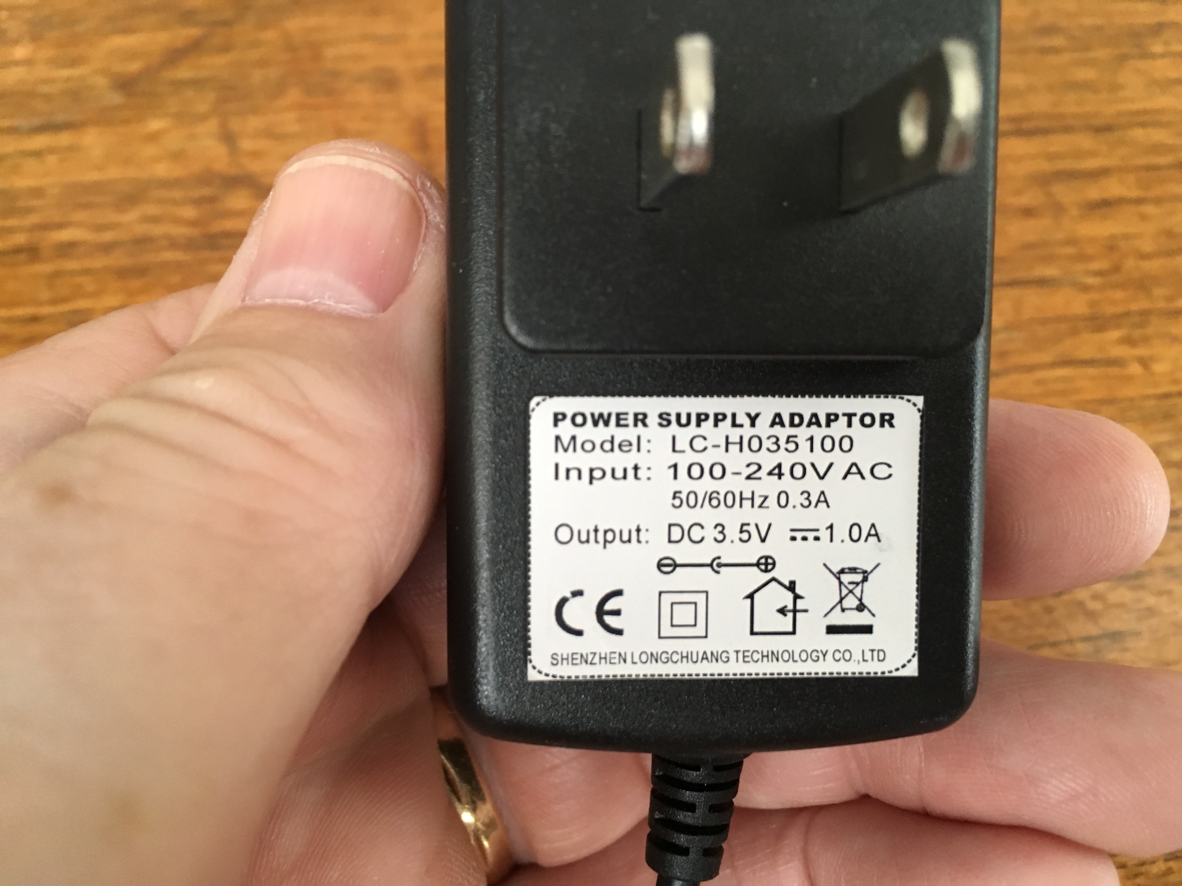
Power
I had measured the bulbs in the past and found that 3.4 to 3.5 volts was about right. Two of these wall wart
power supplies on Amazon cost a total of $15.
|
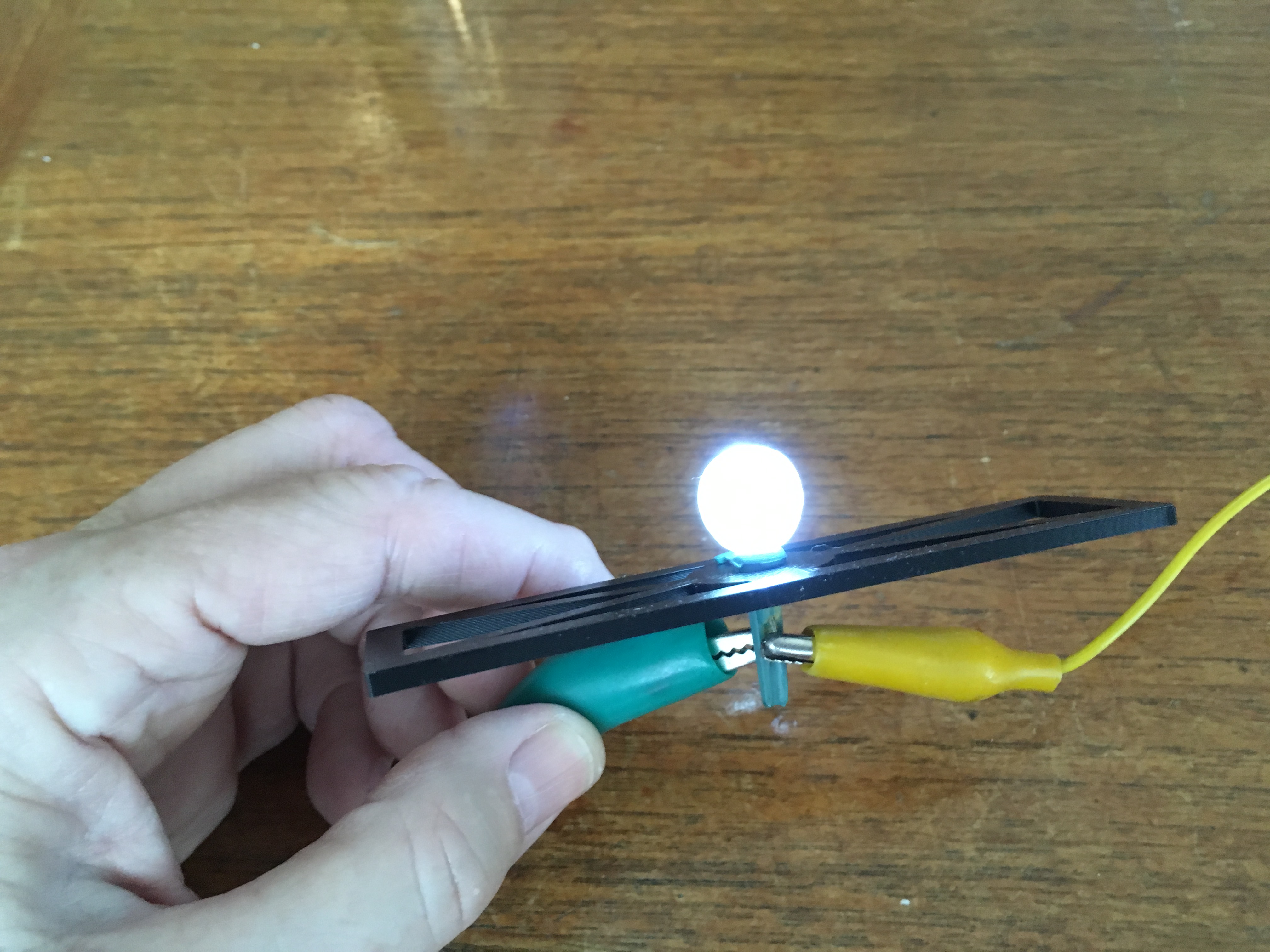
Its Alive
Just checking to be sure the power supplies I bought are a match for the bulbs from WalMart. Yup!
|